Automatic control system for girder erection

An automatic control system and beam erection technology, applied in general control systems, control/adjustment systems, program control, etc., can solve the problems of low erection efficiency, error-prone, safety accidents, etc., so as to improve installation efficiency and reduce the possibility of , Improve the effect of safety protection

Pending Publication Date: 2020-11-17
CHINA COMM 2ND NAVIGATIONAL BUREAU 2ND ENG
View PDF0 Cites 9 Cited by
  • Summary
  • Abstract
  • Description
  • Claims
  • Application Information

AI Technical Summary

Problems solved by technology

[0003] Aiming at the deficiencies existing in the prior art, the present invention proposes an automatic beam erection control system to solve the technical problems in the prior art that the erection efficiency of the beam erection is low when the manual operation is used, which is prone to errors and leads to safety accidents

Method used


Image

  • Automatic control system for girder erection
  • Automatic control system for girder erection
  • Automatic control system for girder erection

Examples


Embodiment 1

[0047] The invention provides an automatic control system for erecting beams, including:

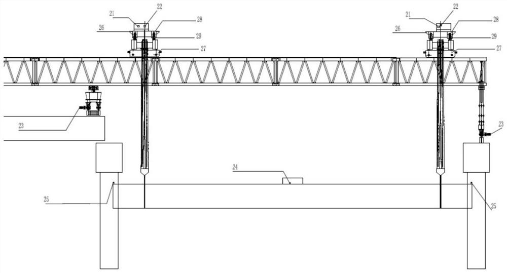
[0048] The RTK receiver 21 is located beside the winch of the crane of the beam erecting equipment, and is used to locate the spatial coordinates of the crane;

[0049] The hoisting height encoder 22 is arranged on the main shaft of the hoist of the crane of the beam erecting equipment, and is used for positioning the spatial coordinates of the spreader;

[0050] The main girder control station is located in the operating room of the girder erection equipment, and communicates with the RTK receiver 21 and the hoisting height encoder 22; Coordinates; it is also used to automatically generate beam erection schemes and send beam erection instructions according to the spatial coordinates of the crane, the spatial coordinates of the spreader and the boundary conditions of the beam erection control;

[0051] The crane control station is located on the traversing trolley of the crane of the gi...

Embodiment 2

[0081] In the process of lifting the beam, safety protection is particularly important. In order to solve the problem of safety protection in the construction process, further optimization is carried out on the basis of Embodiment 1, and relevant measures for safety protection are implemented by using safety protection devices. In this embodiment, the safety protection device includes an inclination sensor 24, an anti-collision indicating device 25, a load sensor 26, and an RFID positioning device. Such as figure 2 As shown, the details are as follows:

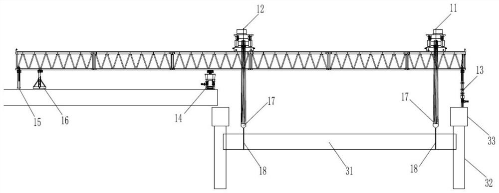
[0082] The portable inclination sensor 24 is placed on the prefabricated beam 31 , and the specific position is not limited. In this embodiment, it is described as an example, and placed on the upper surface of the prefabricated beam 31 by adsorption. The detection signal of the inclination sensor 24 is sent to the control system through its own wireless transmission module. When it is detected that the change in the longi...


PUM


Abstract

The invention provides an automatic control system for girder erection, which comprises an RTK receiver arranged beside a winch of a girder erection equipment crown block and used for positioning space coordinates of the crown block; a lifting height encoder which is arranged on a winch main shaft of a girder erection equipment crown block and is used for positioning space coordinates of the lifting appliance; a main beam control station which is arranged in an operation room of the beam erecting equipment and is in communication connection with the RTK receiver and the lifting height encoder;the main beam control station is used for receiving crown block space coordinates and lifting appliance space coordinates; a beam erecting scheme is automatically generated, and a beam erecting instruction is sent; a crown block control station which is arranged on a transverse moving trolley of the beam erecting equipment crown block, is electrically connected with the main beam control stationand is used for controlling the lifting, transverse moving and longitudinal moving of the lifting appliance; and a supporting leg control station which is arranged on the supporting legs of the beam erecting equipment, is electrically connected with the main beam control station and is used for controlling the whole machine transverse movement of the supporting legs. The technical problems that inthe prior art, when a girder is erected through manual operation, erecting efficiency is low, errors are prone to occurring, and safety accidents are caused can be solved.

Description

technical field [0001] The invention relates to the technical field of highway and railway bridge engineering construction, in particular to an automatic control system for erecting beams. Background technique [0002] In highway and railway engineering, when carrying out bridge construction, with the increasing requirements for bridge assembly, more and more bridge projects use prefabricated beam on-site installation technology for construction. Prefabricated girders are mostly installed on-site by bridge erecting machines, but the current automation control level of bridge erecting machines is very low, and the beam erection operation is almost entirely dependent on manual control. For beam erection conditions with more complex processes, manual operation requires more operators to work together, the erection efficiency is low, and it is easy to make mistakes, leading to safety accidents. Contents of the invention [0003] Aiming at the deficiencies in the prior art, th...

Claims


Application Information

Patent Timeline
Patent Type & Authority Applications(China)
IPC IPC(8): G05B19/418E01D21/00
CPCE01D21/00G05B19/4185G05B19/41875
Inventor 周平姚笛刘景红刘昌义杜权傅少华罗冬春张少平吴小勇林树奎詹光善贺太金陈强赵洵孙泽
Owner CHINA COMM 2ND NAVIGATIONAL BUREAU 2ND ENG
Why Eureka
Try Eureka