Boundary detection method of self-walking equipment and self-walking equipment

A detection method and self-propelled technology, applied in transportation and packaging, two-dimensional position/channel control, instruments, etc., can solve problems such as machine misidentification and affecting mowing operations, so as to avoid misjudgment, improve judgment accuracy, The effect of improving the accuracy of boundary judgment

Active Publication Date: 2020-11-17
NANJING SUMEC INTELLIGENT TECH CO LTD
View PDF6 Cites 3 Cited by
  • Summary
  • Abstract
  • Description
  • Claims
  • Application Information

AI Technical Summary

Problems solved by technology

When metal objects are used as the boundary, there may be other metal debris in the operating area of ​​the machine, such as nuts scattered in the grass, which will cause the machine to be misidentified and affect the mowing operation

Method used


Image

  • Boundary detection method of self-walking equipment and self-walking equipment
  • Boundary detection method of self-walking equipment and self-walking equipment

Examples


Embodiment Construction

[0033] The present invention will be described in further detail below in conjunction with the accompanying drawings.

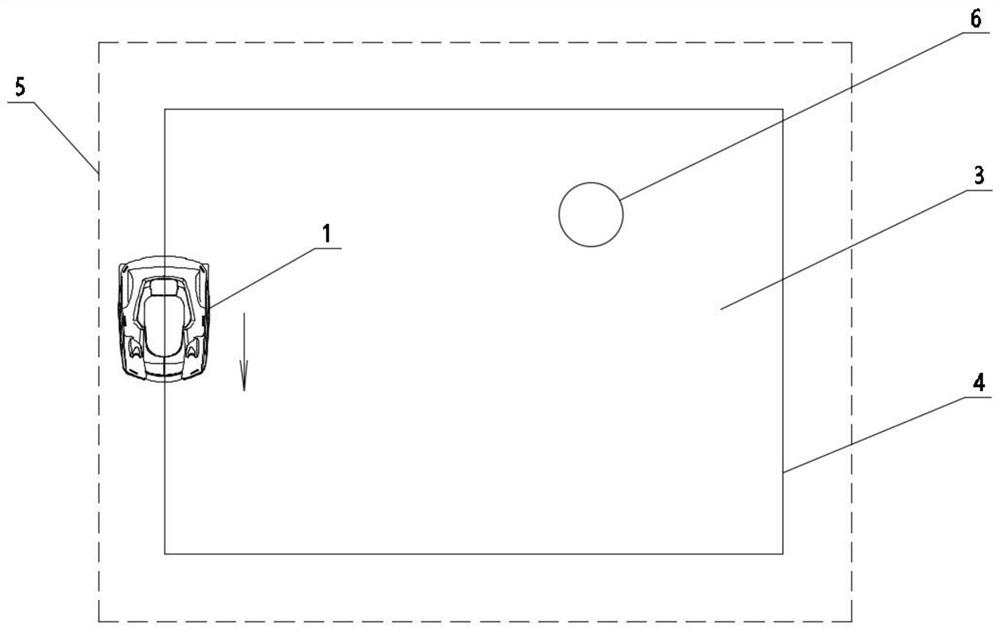
[0034] The boundary detection method of the self-propelled equipment of the present invention is applicable to various self-propelled equipment, and can realize the recognition of the boundary of the working area and obstacles of the self-propelled equipment. This embodiment takes a lawn mowing robot as an example to describe in detail.

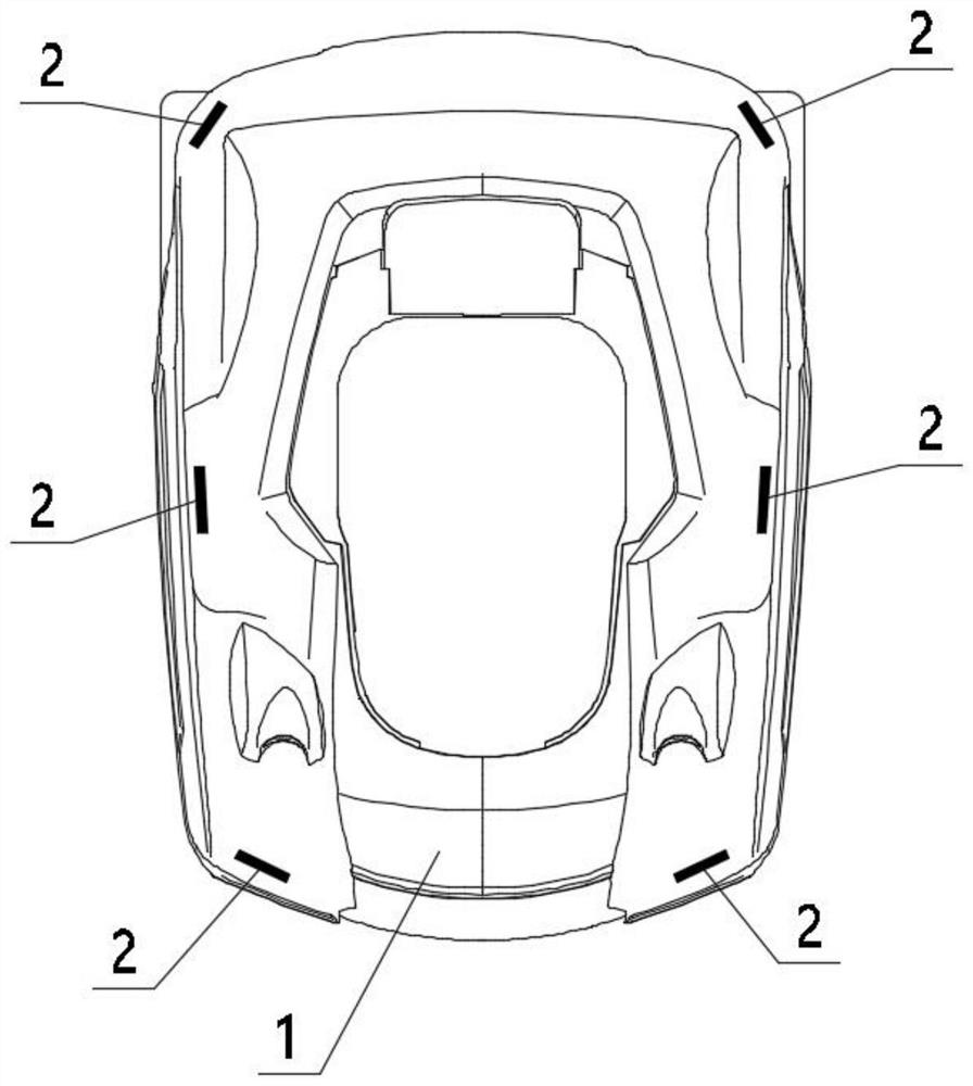
[0035] Such as figure 1 In the lawn mowing robot shown, sensors 2 are evenly distributed around the lawn mowing robot 1 . The sensors are arranged on both sides of the mowing robot, and at least two are arranged on each side. In this embodiment, three sensors are arranged on each side of the mowing robot, which are respectively located at the head, tail and middle of the mowing robot.

[0036] The sensor is a metal detector, which uses the principle of electromagnetic induction and uses a coil with alternating current to ge...


PUM


Abstract

The invention discloses a boundary detection method of self-walking equipment and the self-walking equipment. Ferromagnetic metal substances are arranged at the boundary of the working range of the self-walking equipment and/or the periphery of an obstacle in the working range to form a metal boundary; it is determined that whether magnetic field intensity signals, detected by a metal sensor arranged on the self-walking equipment, of metal substances are continuous or not, if the magnetic field intensity signals are continuous, the metal sensor detects the metal boundary, and if the magnetic field intensity signals are discontinuous, the metal sensor does not detect the metal boundary. According to the invention, continuous ferromagnetic metal particles (powder or blocks) are buried or scattered around a required working range or around an obstacle in the working range to form a closed annular metal boundary, metal detectors are arranged around the equipment, when continuous metal substances are detected, the detected metal boundary is regarded as a metal boundary, and actions such as steering are carried out; therefore, misjudgment of metal substances in the mowing area is avoided, the boundary judgment precision is improved, and meanwhile the trouble of wiring is reduced.

Description

technical field [0001] The invention belongs to the technical field of self-propelled equipment, and in particular relates to a boundary detection method of self-propelled equipment and a self-propelled equipment. Background technique [0002] Self-propelled equipment is an intelligent robot capable of continuous and real-time autonomous movement on roads and outdoors. As a kind of self-propelled equipment, the intelligent mowing robot is suitable for clearing vegetation on hills, terraces, plains and other plots, as well as weeds in lawns. Its operation is simple and its work efficiency is high. Common schools, as well as street landscaping, are done with lawn mowers. In foreign countries, many families use lawn mowers to weed their gardens. [0003] Now the self-propelled equipment needs to bury a closed signal line under the ground to mow the work area, and a sensor is installed on the machine to sense the signal from the signal line, so as to ensure that the machine is...

Claims


Application Information

Patent Timeline
Patent Type & Authority Applications(China)
IPC IPC(8): G05D1/02
CPCG05D1/0259G05D2201/0201
Inventor 杨飞黄玉刚周国扬刘楷汪洋
Owner NANJING SUMEC INTELLIGENT TECH CO LTD
Why Eureka
Try Eureka