
Atmospheric pollution prevention and control device for chemical flue gas

A flue gas and chemical technology, which is applied in the field of air pollution prevention and control devices for chemical flue gas, can solve the problems of rising air particles, high dust temperature, and insufficient filtration of toxic and harmful substances, and achieves rapid cooling and good treatment effect.

Inactive Publication Date: 2020-11-20
广西景秀环保科技有限公司
View PDF0 Cites 1 Cited by
  • Summary
  • Abstract
  • Description
  • Claims
  • Application Information

AI Technical Summary

Problems solved by technology

[0003] The existing chemical flue gas treatment is mainly to do a simple filtering process for the flue gas. Some toxic and harmful substances have not been filtered or the filtration is not thorough enough, and the exhausted flue gas contains a large amount of dust, resulting in a significant increase in particulate matter in the air. Moreover, the temperature of these dusts is relatively high, which poses a serious threat to the natural environment near the factory.

Method used


Image

  • Atmospheric pollution prevention and control device for chemical flue gas
  • Atmospheric pollution prevention and control device for chemical flue gas
  • Atmospheric pollution prevention and control device for chemical flue gas

Examples


Embodiment 1

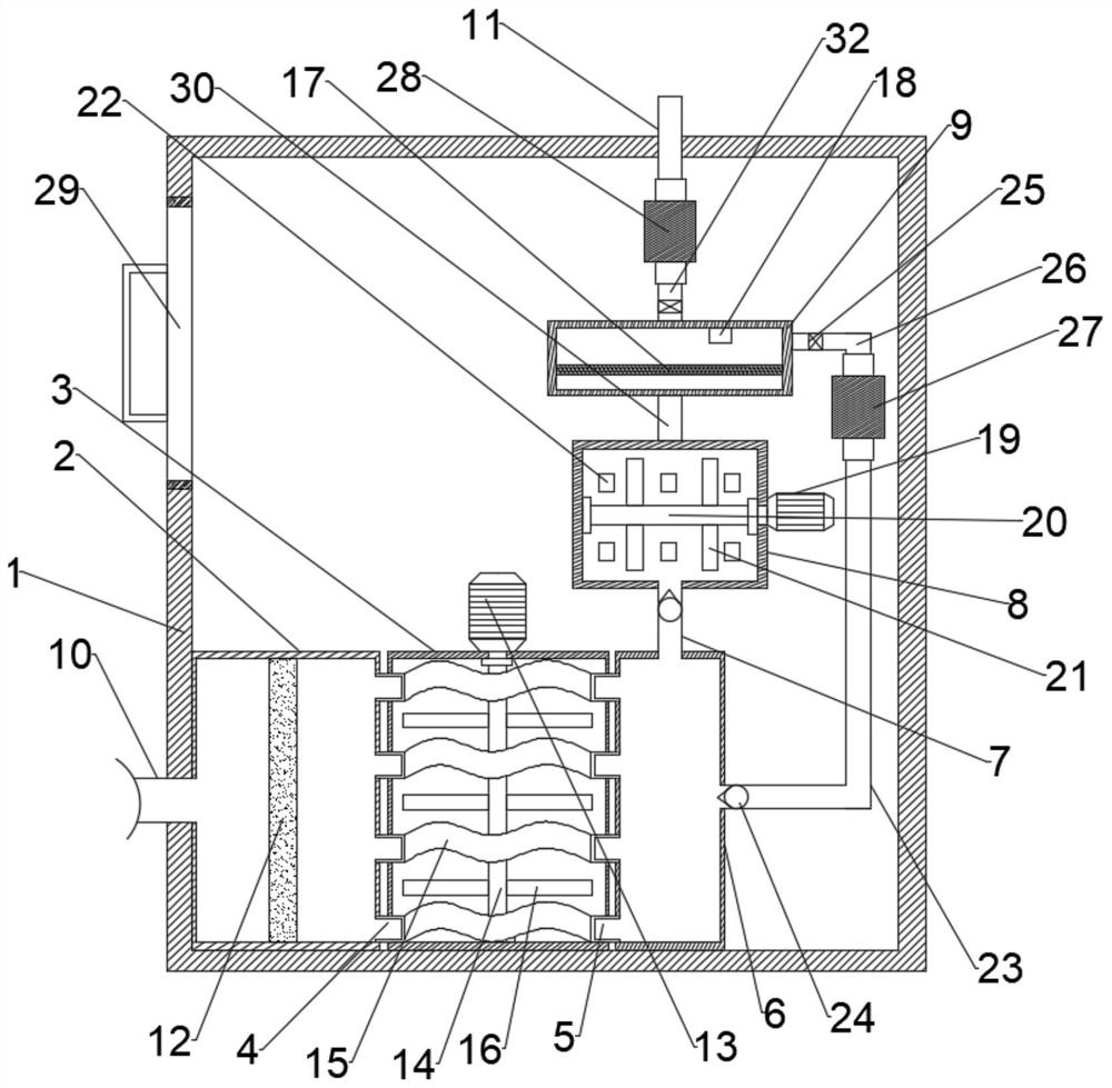
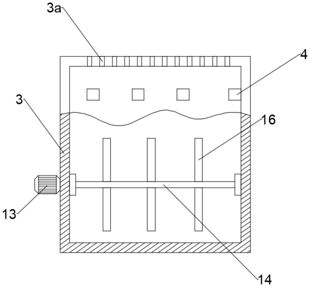
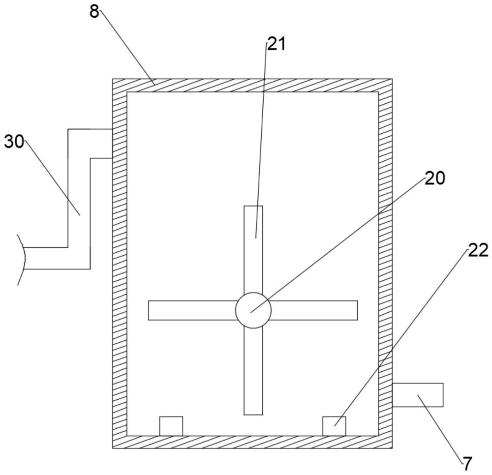
[0025] Combine Figure 1-5 , An air pollution prevention and control device for chemical flue gas, comprising a box body 1, a flue gas inlet pipe 10 and an exhaust pipe 11. The left side of the box body 1 is provided with a flue gas inlet pipe 10 for flue gas to enter the box body 1. , The flue gas inlet pipe 10 passes through the side wall of the box body 1 and is connected to the first filter box 2 inside the box body 1. A first filter screen 12 is installed inside the first filter box 2 and a first filter screen 12 is provided. Used for preliminary filtration of the flue gas and absorbing larger particles in the flue gas. The right side of the first filter box 2 is connected to the cooling box 3 through the first rectangular pipe 4, and the right side of the cooling box 3 passes through the second Two rectangular pipes 5 are connected to the second filter box 6, a serpentine pipe 15 located inside the cooling box 3 is connected between the first rectangular pipe 4 and the se...

Embodiment 2

[0033] Combine figure 1 with 5 , An air pollution prevention device for chemical flue gas. This embodiment further limits the device on the basis of Embodiment 1.

[0034] The drying plate 17 is provided with uniformly distributed air holes 17a, and the walls of the air holes 17a are provided with a desiccant 17b, the uniform air holes 17a and the air holes 17a are provided with a desiccant 17b on the wall to fully absorb the smoke from the chemical The liquid taken away in the reaction liquid facilitates the discharge of flue gas.

[0035] A maintenance inlet cover 29 is provided on the left side of the box body 1, and a maintenance inlet cover 29 is provided to facilitate the opening and regular replacement of the first filter screen 12, the second filter screen 31, the chemical reaction liquid, and the repair and maintenance of the equipment inside. The flue gas purification treatment proceeded smoothly.


PUM


Abstract

The invention discloses an atmospheric pollution prevention and control device for chemical flue gas. The device comprises a box body, a flue gas inlet pipe and an exhaust pipe, the flue gas inlet pipe is arranged on the left side of the box body, the flue gas inlet pipe penetrates through the side wall of the box body and is connected to a first filter box in the box body, a first filter screen is installed in the first filter box, the right side of the first filter box is connected with a cooling box through a first rectangular pipeline, and the right side of the cooling box is connected with a second filter box through a second rectangular pipeline. According to the invention, flue gas is preliminarily filtered through the first filter screen, the cooling box cools the flue gas, the second filter screen finely filters the flue gas, the chemical reaction treatment box absorbs and decomposes harmful substances in the flue gas, and the solenoid valve, the second sucking pump, the thirdconnecting pipe and the second connecting pipe are matched to carry out secondary chemical reaction treatment on the flue gas which does not reach the standard, therefore, the flue gas is fully purified, pollution control is carried out, and the treatment effect is good.

Description

Technical field [0001] The invention relates to the technical field of air pollution prevention and control, in particular to an air pollution prevention and control device for chemical flue gas. Background technique [0002] Air pollution prevention and control is mainly to control the problem of air pollution. There are many factors in air pollution, including automobile exhaust emissions, chemical flue gas emissions and flue gas emissions from some thermal power plants. If not treated in time, it will cause serious pollution to the atmosphere. For example, now Common haze is extremely harmful to human health and can induce many cancers. [0003] The existing chemical flue gas treatment is mainly to simply filter the flue gas. Some toxic and harmful substances are not filtered or not thoroughly filtered, and the emitted flue gas includes a large amount of dust, which causes a significant increase in particulate matter in the air. Moreover, the dust temperature is relatively high...

Claims


Application Information

Patent Timeline
Patent Type & Authority Applications(China)
IPC IPC(8): B01D46/12B01D46/00B01D53/78B01D53/86
CPCB01D46/12B01D53/86B01D53/78B01D2258/0283B01D46/62
Inventor 崔景山
Owner 广西景秀环保科技有限公司
Learn More