
Continuous production method and equipment for built-in condenser forming and attaching

A production method and condenser technology, applied in the continuous production method and equipment field of built-in condenser forming and pasting, can solve the problems of unstable manual operation, affecting product quality, low production efficiency, etc., and achieve no difference in batch production Effects of production, equipment and operation space saving, and efficiency improvement

Active Publication Date: 2020-11-20
青岛恒恩智能装备有限公司
View PDF11 Cites 2 Cited by
  • Summary
  • Abstract
  • Description
  • Claims
  • Application Information

AI Technical Summary

Problems solved by technology

The following problems exist: ①The amount of labor is large. In the existing production line, there are 2-3 people for blanking, flaring, and zinc removal, 4-5 people for pipe bending, and 4-5 people for upper casing line and glue application. 10-13 people; ②The manual operation is slow, the continuity between processes is poor, and the average processing time of a single product is long; ③It takes up a lot of space, and it needs a blanking machine, a zinc remover, a belling machine, a coil machine, a tooling car, a casing wire, Gluing devices, etc., and each machine needs to leave room for operation; ④Manual operation is mainly, and there are human factors such as manual operation instability that affect product quality
The above problems lead to low production efficiency and high production costs

Method used


Image

  • Continuous production method and equipment for built-in condenser forming and attaching
  • Continuous production method and equipment for built-in condenser forming and attaching
  • Continuous production method and equipment for built-in condenser forming and attaching

Examples


Embodiment

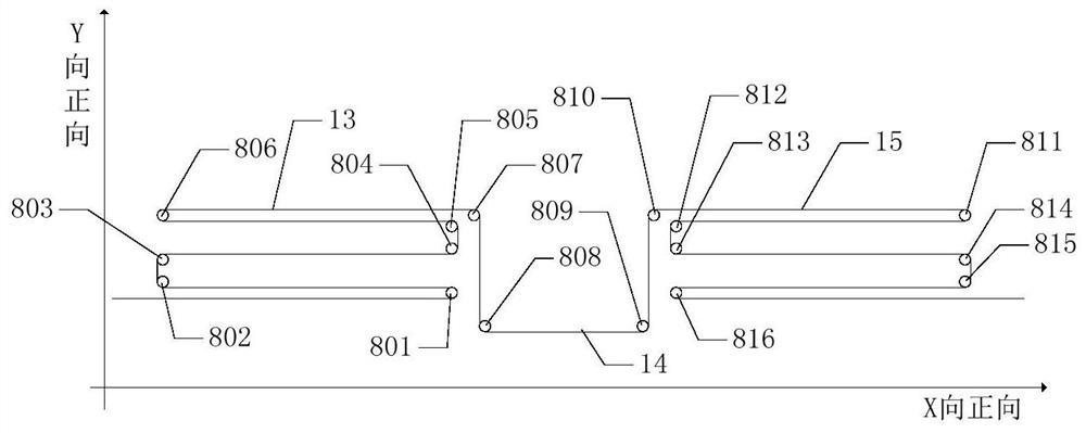
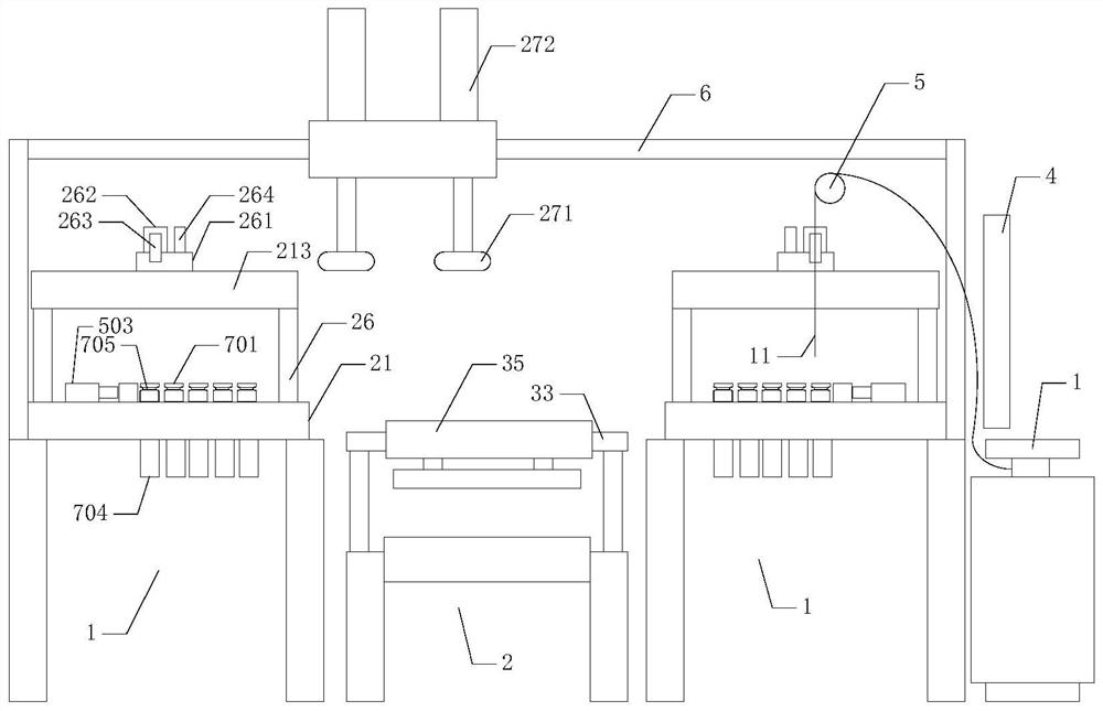
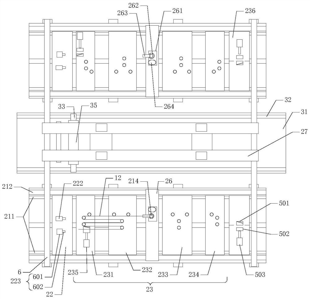
[0051] Example: Combine Figure 1-11 , a continuous production method for forming and applying a built-in condenser, the steps are as follows:

[0052] S100, cutting the raw material of the condenser tube,

[0053] S200. Forming of the condenser, end treatment, bending and cutting of the raw material of the condenser tube to obtain the condenser,

[0054] S300, the shell plate is conveyed on the shell line to the sticking area to stop, and is firmly attracted by the electromagnet, and the condenser obtained in step S200 is directly transferred to the shell plate at the sticking area,

[0055] S400. Applying the condenser, start the glue applying device to apply the glue, complete the application, cut off the electromagnet, and the shell wire transports the shell plate that has been pasted.

[0056] Further, the end treatment in step S200 includes surface dezincification or a combination of surface dezincification and flaring treatment.

[0057] Further, the condenser formed...


PUM


Abstract

The invention provides a continuous production method and equipment for built-in condenser forming and attaching, and relates to the technical field of the built-in condenser forming and attaching. The continuous production method comprises the following steps of: carrying out condenser pipe raw material blanking; carrying out condenser forming, and carrying out end part processing, bending forming and cutoff processing on condenser pipe raw materials to obtain a condenser; on a shell line, conveying a shell plate to an attaching area to stop, tightly attracting the shell plate by an electrified magnet, and directly moving the condenser to the shell plate in the attaching area; and starting a rubberizing device to carry out rubberizing, finishing attaching, cutting off the electrified magnet, and conveying the shell plate which finishes being attached through the shell line. The continuous production equipment comprises a forming part, an attaching part, a transferring tool for hoisting the condenser, and a controller, wherein the forming part carries out the end part processing and the bending forming on the condenser pipe raw materials, and the attaching part attaches the condenser to the shell plate. By use of the continuous production method and equipment, built-in condenser forming and attaching equipment can be subjected to integrated design, continuous forming and attaching production can be carried out, efficiency is effectively improved, cost is lowered, and product quality is stable.

Description

technical field [0001] The invention relates to the technical field of forming and pasting of built-in condensers, in particular to a continuous production method and equipment for forming and pasting of built-in condensers. Background technique [0002] The condenser is a key component of the refrigeration system of an appliance. A condenser is arranged inside the housing of the refrigerator or freezer, and the condensation pipe is pasted on the housing components. The shell part is a part of the refrigerator or freezer shell. The shell part includes two opposite side plates and a connecting plate between the two side plates. The shell part is mostly a one-piece structure, and it is a flat shell before bending. pieces. [0003] At present, the forming and applying process of the built-in condenser includes: the condenser tube is unloaded from the disc, and then goes through step-by-step procedures such as flaring, zinc removal, manual bending, cutting, manual casing wire,...

Claims


Application Information

Patent Timeline
IPC IPC(8): B23P15/26B23Q3/06F25B39/04
CPCB23P15/26B23Q3/062F25B39/04
Inventor 贾德刚
Owner 青岛恒恩智能装备有限公司
Learn More