
Identification instrument for detecting biological spots on criminal investigation site

An identification instrument and biological technology, applied in the field of identification instruments, can solve the problems of long detection and analysis time period, reduced analysis efficiency, and many interfering substances, and achieves the effect of reducing false positives and false positives, flexible and convenient detection, and reducing false positives.

Pending Publication Date: 2020-11-20
INST OF FORENSIC SCI OF MIN OF PUBLIC SECURITY
View PDF7 Cites 2 Cited by
  • Summary
  • Abstract
  • Description
  • Claims
  • Application Information

AI Technical Summary

Problems solved by technology

In actual use, various light sources of many brands can find spots, but there is no relevant equipment that can directly distinguish the types of spots on the spot that can be used in practice
[0005] To sum up, the ultraviolet developing lamp used in the criminal investigation scene is based on the judgment of human eyes or photography, and there are too many interference objects, which are easy to be false positive; forensic DNA detection technology needs to sample suspicious objects, and then send them to the laboratory for laboratory analysis, and the detection and analysis time The cycle is long, it is difficult to guarantee timeliness, and its analysis efficiency largely depends on the accurate acquisition of criminal investigation site inspection materials. In order to ensure that no evidence is missed, more invalid evidence analysis is usually required, which greatly reduces the analysis efficiency

Method used


Image

  • Identification instrument for detecting biological spots on criminal investigation site
  • Identification instrument for detecting biological spots on criminal investigation site
  • Identification instrument for detecting biological spots on criminal investigation site

Examples


Embodiment Construction

[0029] Exemplary embodiments of the present invention will be described in more detail below with reference to the accompanying drawings. Although exemplary embodiments of the present invention are shown in the drawings, it should be understood that the invention may be embodied in various forms and should not be limited to the embodiments set forth herein. Rather, these embodiments are provided for more thorough understanding of the present invention and to fully convey the scope of the present invention to those skilled in the art.

[0030] It should be understood that the terminology used herein is for the purpose of describing particular example embodiments only and is not intended to be limiting. As used herein, the singular forms "a", "an" and "the" may also be meant to include the plural forms unless the context clearly dictates otherwise. The terms "comprising", "comprising" and "having" are inclusive and thus indicate the presence of stated features, steps, operation...


PUM


Abstract

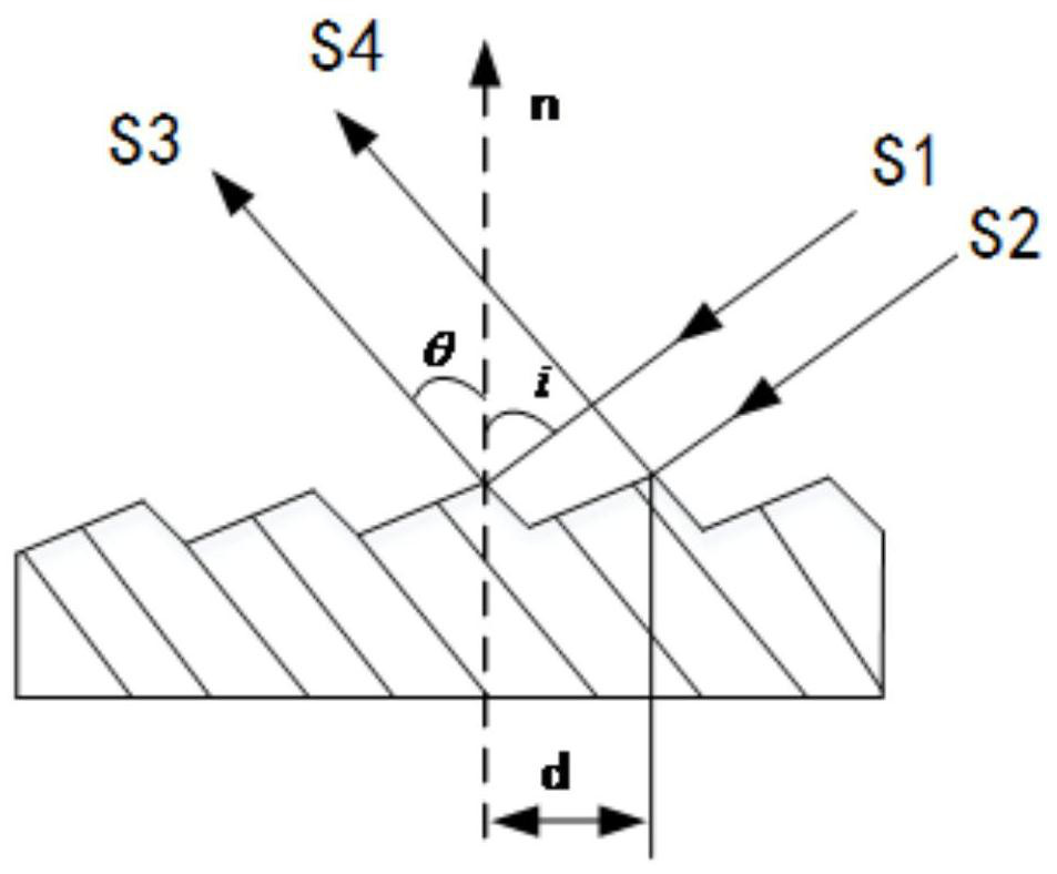
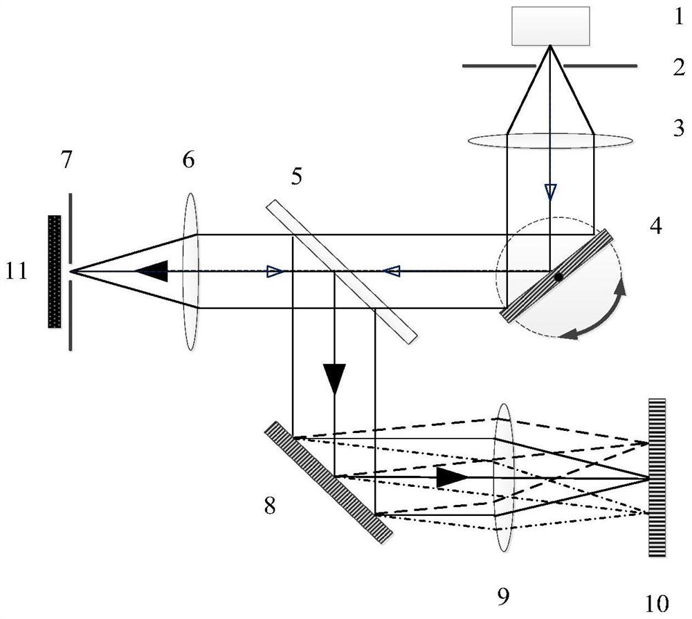
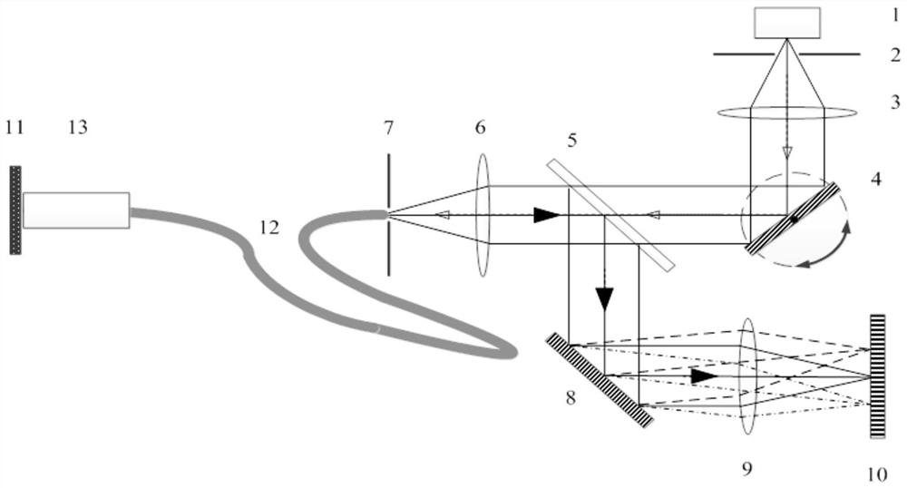
The invention relates to an identification instrument for detecting biological spots on a criminal investigation site. The identification instrument comprises an excitation light source, a light source diffraction grating, a focusing coupling mirror, a fluorescence diffraction grating, a spectral focusing imaging mirror and a photoelectric detector array. Excitation light emitted by the excitationlight source is emitted to the light source diffraction grating through the light source slit, light with different wavelengths is emitted to the focusing coupling mirror through the semi-reflectingand semi-transmitting beam splitter, and the focusing coupling mirror is used for converging the excitation light with different wavelengths and emitting the excitation light to a measured target through the exit slit. Excited fluorescence of a measured target is collected by the focusing coupling mirror through the exit slit; the laser beam is emitted to a fluorescence diffraction grating througha semi-reflecting and semi-transmitting beam splitter; the fluorescence diffraction grating is used for separating a multicolor fluorescence spectrum signal into monochromatic light according to a wavelength space, each monochromatic fluorescence component is focused and imaged to different positions through the spectrum focusing imaging lens, and the photoelectric detector array is used for collecting fluorescence spectrum signals at different positions to complete biological spot detection of a detected target.

Description

technical field [0001] The invention relates to a recognition instrument used for biological spot detection on the scene of criminal investigation, and relates to the technical field of criminal investigation. Background technique [0002] DNA detection technology and related instruments, as an important technical means for public security to investigate and solve crimes and fight crimes, are increasingly playing an important role in the identification of criminal suspects, paternity identification and serial merger cases. With the development of science and technology, forensic DNA detection technology has experienced many technical innovations such as multi-site DNA fingerprint analysis, amplified fragment length polymorphism analysis, mitochondrial detection technology, RNA detection technology, etc., and is still developing, but the above The realization of technology is based on the accurate acquisition of inspection materials. At present, fluorescence spectroscopy tec...

Claims


Application Information

Patent Timeline
Patent Type & Authority Applications(China)
IPC IPC(8): G01N21/64
CPCG01N21/6402
Inventor 畅晶晶聂昊张瑾王冲张广峰徐小玉王枫熊胜军杨雪莹郝金萍张颖朱典周辉周毅刘开会
Owner INST OF FORENSIC SCI OF MIN OF PUBLIC SECURITY
Learn More