Multilayer liquid distribution device and method for falling film reboiler
A liquid distribution device and liquid distribution technology, applied in separation methods, chemical instruments and methods, evaporator accessories, etc., can solve the problems of dry wall of falling film tube, difficult to fix effectively, unstable working performance, etc., to reduce resistance, Good uniformity and avoid uneven distribution of liquid
- Summary
- Abstract
- Description
- Claims
- Application Information
AI Technical Summary
Problems solved by technology
Method used
Image
Examples
Embodiment 1
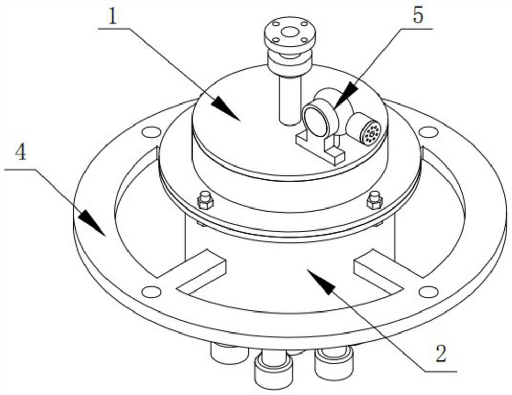
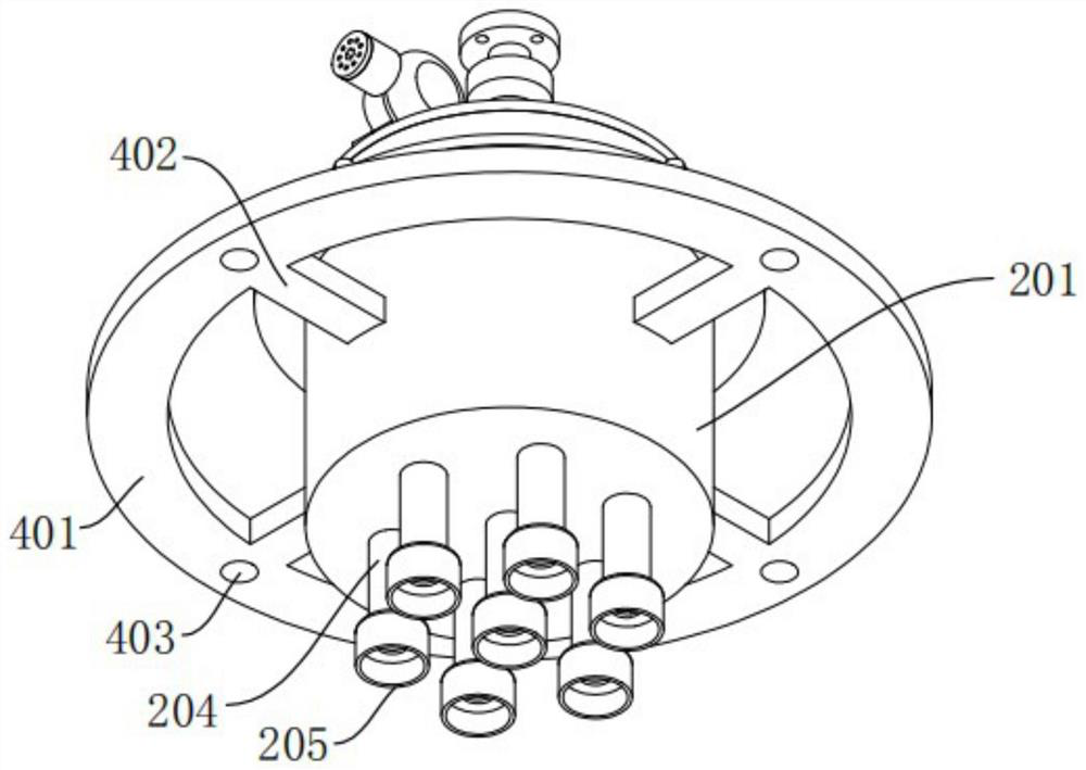
[0041] A multi-layer liquid distribution device for a falling film reboiler, such as figure 1 As shown, it includes the first layer of liquid distribution mechanism 1 and the second layer of liquid distribution mechanism 2;
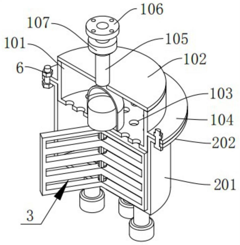
[0042] Among them, such as figure 1 with 3 As shown, the first layer of liquid distribution mechanism 1 includes a first cylindrical shell 101, an upper cover plate 102 and a liquid inlet pipe 105, the bottom of the first cylindrical shell 101 is a closed structure, and the first The upper part of a cylindrical shell 101 is an open structure, and the bottom wall of the first cylindrical shell 101 is uniformly provided with a plurality of first evenly distributed holes 103, and the outside of the first cylindrical shell 101 is adjacent to it. The first annular fitting seat 104 is fixedly installed on the upper part, the upper cover plate 102 is fixedly and sealingly installed on the upper part of the first cylindrical housing 101, and the liquid inlet pi...
Embodiment 2
[0050] Such as Figure 3-4 As shown in and 6-8, the difference between this embodiment and Embodiment 1 is that it also includes an anti-sticking wall mechanism 3, and the anti-sticking wall mechanism 3 includes a protective cover 302, a motor 301, a rotating shaft 303 and a scraper 304 , the protective cover 302 is fixedly and sealingly installed at the upper center of the inner bottom wall of the first cylindrical housing 101, the motor 301 is fixedly installed inside the protective cover 302, and the rotating The shaft 303 is installed vertically and fixedly at the center of the bottom wall of the first cylindrical housing 101 through a sealed bearing, and the upper end of the rotating shaft 303 is fixedly connected with the rotating shaft of the motor 301 through a coupling , the scraper 304 is provided with three, and the scraper 304 is fixedly installed on the side of the rotating shaft 303, and the three scraping boards 304 are arranged around the rotating shaft 303 in ...
Embodiment 3
[0053] Such as Figure 1-3 As shown in and 9, the difference between this embodiment and Embodiment 2 is that it also includes a pressurizing mechanism 5, which includes a fan 501, a cylindrical casing 502, an air filter element 503 and a cover 504, the The fan 501 is fixedly installed on the upper part of the upper cover plate 102 through the fixing seat 507, and the air outlet of the fan 501 communicates with the inside of the first cylindrical shell 101 through a pipe 508, and the cylindrical shell 502 is fixedly installed at the air inlet of the fan 501, and the end of the cylindrical shell 502 away from the fan 501 is an open end, and the air filter element 503 is packaged in the cylindrical housing 503 through the cover 504 Inside the casing 502, the cover 504 is screwed on the open end of the cylindrical casing 502, and several ventilation holes 505 are evenly opened on the cover 504, and the outer surface of the cover 504 A hexagonal slot 506 is also reserved at the c...
PUM
 Abstract
Description
Claims
Application Information
 - R&D
- Intellectual Property
- Life Sciences
- Materials
- Tech Scout
- Unparalleled Data Quality
- Higher Quality Content
- 60% Fewer Hallucinations
Browse by: Latest US Patents, China's latest patents, Technical Efficacy Thesaurus, Application Domain, Technology Topic, Popular Technical Reports.
© 2025 PatSnap. All rights reserved.Legal|Privacy policy|Modern Slavery Act Transparency Statement|Sitemap|About US| Contact US: help@patsnap.com


