Axial bolt type camshaft automatic positioning device and using method thereof

A technology of automatic positioning and camshaft, which is applied in the direction of positioning device, clamping, support, etc., can solve the problems of high production cost, weakening of camshaft fatigue resistance, complex structure of grinding chuck, etc., achieve low processing cost and reduce labor force Effect of labor intensity, improvement of processing quality and production efficiency

Active Publication Date: 2020-11-24
ASIMCO CAMSHAFT YIZHENG
View PDF13 Cites 6 Cited by
  • Summary
  • Abstract
  • Description
  • Claims
  • Application Information

AI Technical Summary

Problems solved by technology

Because the positioning pin hole is located on the outer surface of the journal, the structure of the grinding chuck is complicated and the production cost is high, and the radial pin hole on the outer surface of the journal is easy to produce pressure concentration, thereby weakening the overall anti-fatigue strength of the camshaft

Method used


Image

  • Axial bolt type camshaft automatic positioning device and using method thereof
  • Axial bolt type camshaft automatic positioning device and using method thereof
  • Axial bolt type camshaft automatic positioning device and using method thereof

Examples


Embodiment Construction

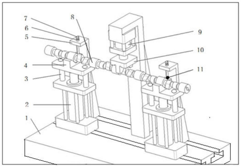
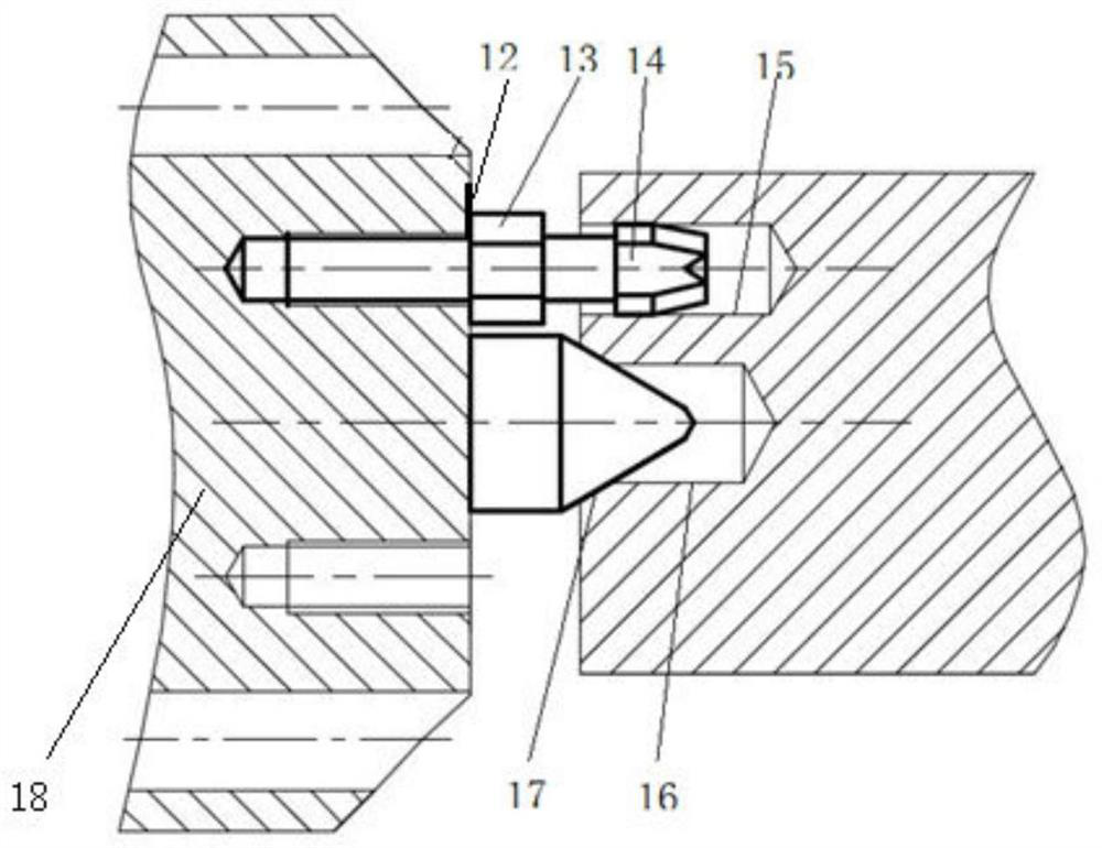
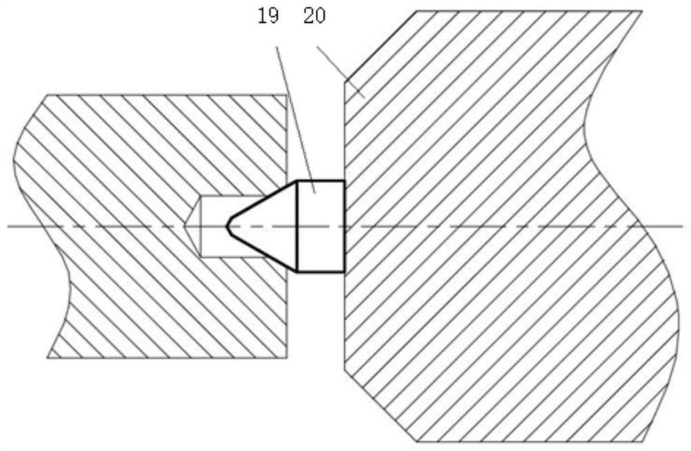
[0035] Take a certain model of 13L automobile engine camshaft as an example. The camshaft is designed with 7 journals and a shaft diameter of Φ40mm, with a length of 1050mm and a weight of 15kg. The left and right end faces are respectively machined with center holes (such as figure 2 , image 3 ), and a positioning hole with a diameter of 10 mm is processed on the left end of the workpiece.

[0036] The device is composed of an end face positioning part, an auxiliary positioning part and a base; the end face positioning part includes a marking line 12, a lock nut 13, a chamfering pin 14, a left top structure (top 17, a top seat 18), a right top structure ( Top 19, top seat 20). The left and right tops (17, 19) limit the 5 degrees of freedom of the workpiece. The use of threaded chamfering pins 14 to replace traditional cylindrical pins can prevent over-positioning and can be reliably connected with the center seat 18. The marking line 12 on the top seat 18 and the trimm...


PUM


Abstract

The invention relates to an axial bolt type camshaft automatic positioning device and a using method thereof. The axial bolt type camshaft automatic positioning device is composed of an end face positioning part, an auxiliary pre-positioning part and a base, for the end face positioning part, the end face of a workpiece is positioned by combining double tips and an edge cutting pin, by adopting end face plug pin type positioning, a positioning fixture is obviously simplified compared with a cylindrical surface plug pin type structure, for the auxiliary pre-positioning part, lower air cylindersdrive lower movable V-shaped blocks to move along guide columns, the jacking height of the lower movable V-shaped blocks is controlled through adjustable limiting screws, so that the axis position ofa camshaft is guaranteed, an upper movable V-shaped block is driven by an upper air cylinder to move downwards and makes contact with the outline of the cam peach tip, and circumferential auxiliary positioning of the camshaft is achieved. The whole device completes pre-positioning of the workpiece on a machine tool through the auxiliary positioning part, so that impact between the workpiece and the tips and the edge cutting pin during manual installation is avoided, then rapid installation of the workpiece on the end face tips and the edge cutting pin is guaranteed, the installation auxiliarytime is effectively saved, the labor intensity of workers is relieved, and the positioning quality and the production efficiency are improved.

Description

technical field [0001] The invention relates to a positioning and clamping device, in particular to an axial plug type camshaft automatic positioning device and a using method thereof. Background technique [0002] As a key component of a piston engine, the precision machining of the camshaft plays an important role in the engine manufacturing process. In the process of camshaft machining, high-precision and automatic clamping and positioning are particularly urgent. With the continuous improvement of industrial automation in the manufacturing field in recent years, the efficiency and cost of manual work on the production line have limited the further industrialization of some new processing techniques, so the demand for automation in manufacturing, processing and clamping systems is getting higher and higher. The traditional manual clamping method requires manual installation of the workpiece, and it is difficult to quickly align the tip and trimming pin with the positioni...

Claims


Application Information

Patent Timeline
Patent Type & Authority Applications(China)
IPC IPC(8): B23Q3/00
CPCB23Q3/00
Inventor 李云蕾华希俊田之翔解玄
Owner ASIMCO CAMSHAFT YIZHENG
Why Eureka
Try Eureka