
Device surface precise polishing apparatus for machining production

A technology of precision polishing and mechanical processing, which is applied in the direction of electrolytic process and electrolytic components, etc. It can solve the problems that mechanical processing equipment is easy to shake, sway, inconvenient to place and pick up mechanical equipment, and damage mechanical processing equipment, so as to facilitate electrolytic polishing, Avoid shaking damage and improve stability

Inactive Publication Date: 2020-11-24
李发进
View PDF0 Cites 0 Cited by
  • Summary
  • Abstract
  • Description
  • Claims
  • Application Information

AI Technical Summary

Problems solved by technology

[0003] However, when the current electrolytic method is used to polish the cylindrical mechanical processing production equipment, the cylindrical mechanical processing equipment is picked up by a pick-up mechanism made of tough steel sheets. The tough pick-up mechanism is It is easy to shake and shake when placing and picking up the cylindrical machining equipment inside the electrolytic cell, which will cause the cylindrical equipment to fall when taking and placing it, causing damage to the polished machining equipment, and it is inconvenient to remove the cylindrical machining equipment. Placement and retrieval of machinery and equipment

Method used


Image

  • Device surface precise polishing apparatus for machining production
  • Device surface precise polishing apparatus for machining production
  • Device surface precise polishing apparatus for machining production

Examples


Embodiment Construction

[0017] The technical solutions in the embodiments of the present invention will be clearly and completely described below with reference to the accompanying drawings in the embodiments of the present invention. Obviously, the described embodiments are only a part of the embodiments of the present invention, but not all of the embodiments. Based on the embodiments of the present invention, all other embodiments obtained by those of ordinary skill in the art without creative efforts shall fall within the protection scope of the present invention.

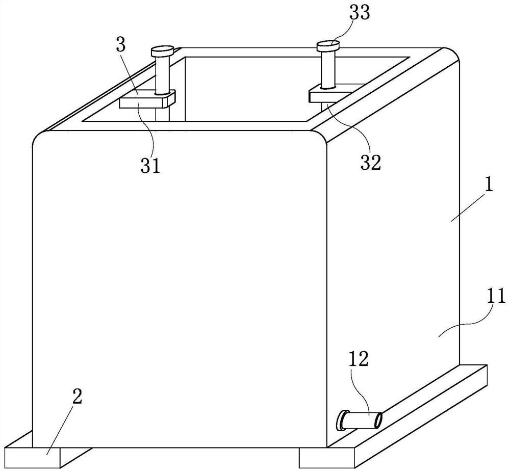
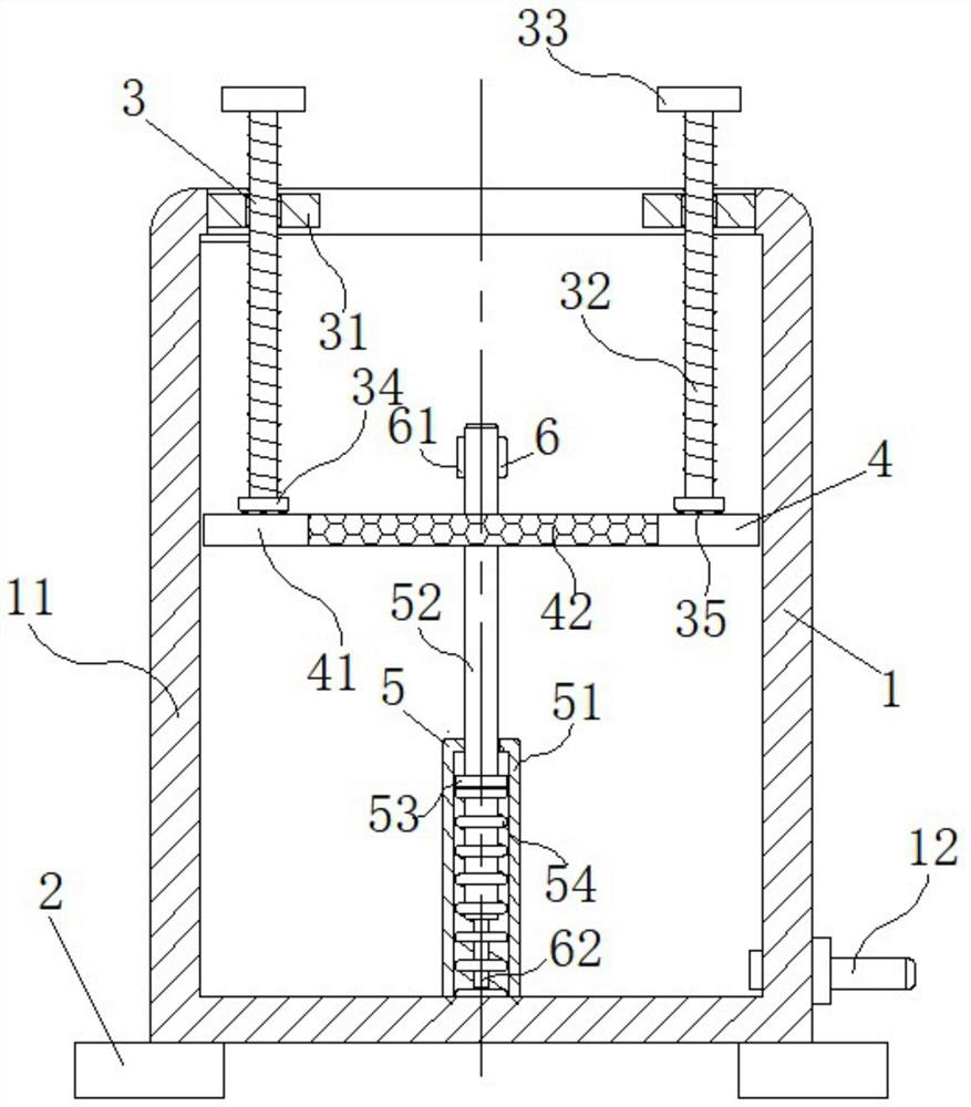
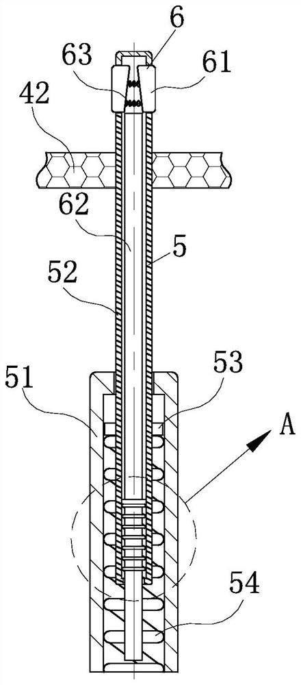
[0018] see Figure 1-4 As shown, a precision polishing device for the surface of mechanical processing production equipment includes a polishing mechanism 1 and a pressing mechanism 3 installed inside the polishing mechanism 1, the polishing mechanism 1 includes an electrolytic cell 11, and the pressing mechanism 3 is installed Inside the electrolytic cell 11 with the top opening, the pressing mechanism 3 includes a mounting plate 31,...


PUM


Abstract

The invention discloses a device surface precise polishing apparatus for machining production, comprising a polishing mechanism, an electrolytic cell, a base, a pressing mechanism, a mounting plate, studs, pressing discs, a support mechanism, a protection plate, a filter plate, an extension mechanism, a fixed column, a sliding rod, a first limiting ring, a pressure spring, and a supporting mechanism. The invention has the beneficial effects that: a cylindrical machining device is put at the top of the filter plate; two studs are rotated to move down; two pressing discs at the bottoms of the studs press down the protection plate on the side wall of the filter plate; moreover, the sliding rod shrinks into the fixed column, and the pressure spring shrinks; and the cylindrical machining deviceput on the surface of the filter plate is immersed into electrolytic water in the electrolytic cell, on the one hand, the descending and ascending stability of the cylindrical machining device put onthe surface of the filter plate is guaranteed to prevent damage of the cylindrical machining device caused by shaking, and on the other hand, the operation is simple, and the cylindrical machining device is conveniently placed and taken to facilitate electrolytic polishing.

Description

technical field [0001] The invention relates to a polishing device, in particular to a precision polishing device for the surface layer of mechanical processing production equipment, belonging to the technical field of mechanical equipment polishing. Background technique [0002] Polishing refers to the use of mechanical, chemical or electrochemical action to reduce the surface roughness of the workpiece to obtain a bright and smooth surface. It is a technology that uses polishing tools and abrasive particles or other polishing media to modify the surface of the workpiece. Using the metal workpiece as the anode, electrolysis is performed in a suitable electrolyte to selectively remove the rough surface and improve the surface finish. Called electrolytic polishing. Electropolishing can increase the corrosion resistance of stainless steel, reduce the resistance of electrical contact points, prepare metallographic grinding sheets, improve the reflective performance of lighting...

Claims


Application Information

Patent Timeline
Patent Type & Authority Applications(China)
IPC IPC(8): C25F7/00C25F3/16
CPCC25F3/16C25F7/00
Inventor 李发进李聪
Owner 李发进
Learn More