Optical fiber sensor hot-melting packaging belt, metal pressure pipeline and manufacture method of metal pressure pipeline

A fiber optic sensor and metal pipeline technology, applied in pipeline systems, non-detachable pipe connections, pipes/pipe joints/fittings, etc., can solve the problems of low mechanical strength and failure, and achieve the effect of accurate monitoring of corrosion status

Inactive Publication Date: 2020-11-24
HUBEI SANJIANG AEROSPACE GRP HONGYANG ELECTROMECHANICAL
View PDF12 Cites 0 Cited by
  • Summary
  • Abstract
  • Description
  • Claims
  • Application Information

AI Technical Summary

Problems solved by technology

[0002] Corrosion of metal pipelines is the main cause of pipeline failure accidents. According to the analysis provided by the domestic metal pressure pipeline safety big data system, more than 80% of metal pipeline corrosion failures are caused by the combined effects of pitting corrosion and stress corrosion, and the failure parts are mainly located in As we all know, the mechanical strength of metal pipe welds is lower than that of the base metal, and the pressure strain of the welds is greater than that of the base metal, which means that the early form of corrosion is slow pitting at the welds , the clustered pitting corrosion develops into cracks under the action of stress in the later stage, and finally the cracks rapidly expand into cracks and cause failure accidents

Method used


Image

  • Optical fiber sensor hot-melting packaging belt, metal pressure pipeline and manufacture method of metal pressure pipeline
  • Optical fiber sensor hot-melting packaging belt, metal pressure pipeline and manufacture method of metal pressure pipeline
  • Optical fiber sensor hot-melting packaging belt, metal pressure pipeline and manufacture method of metal pressure pipeline

Examples


Embodiment Construction

[0038] The technical solutions in the embodiments of the present invention will be clearly and completely described below in conjunction with the accompanying drawings in the embodiments of the present invention. Obviously, the described embodiments are only some of the embodiments of the present invention, not all of them. Based on The embodiments of the present invention and all other embodiments obtained by persons of ordinary skill in the art belong to the protection scope of the embodiments of the present invention.

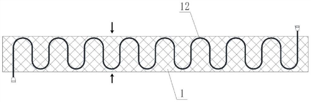
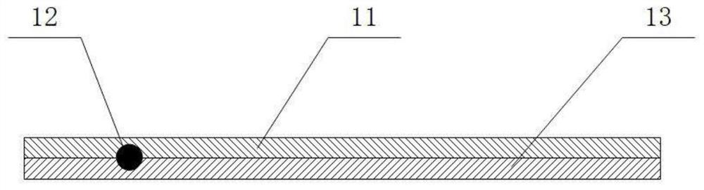
[0039] see figure 1 , figure 1 A structural schematic diagram of a fiber optic sensor hot-melt packaging tape provided in this embodiment, figure 2 for figure 1 The cross-sectional view at the arrow, the optical fiber sensor hot-melt packaging tape 1 specifically includes: a hot-melt anti-corrosion layer 11 stacked up and down, a first detection optical fiber 12 and a hot-melt base layer 13 .

[0040] The first detection optical fiber 12 is arranged betw...


PUM


Abstract

The invention relates to the technical field of metal pipeline monitoring, in particular to an optical fiber sensor hot-melting packaging belt, a metal pressure pipeline and a manufacture method of the metal pressure pipeline. The optical fiber sensor hot-melting packaging belt is used for monitoring the corrosion state of a pipeline welding line and comprises a hot melting anticorrosion layer, afirst detection optical fiber and a hot melting base layer, wherein the hot melting anticorrosion layer, the first detection optical fiber and the hot melting base layer are vertically overlaid; and the first detection optical fiber is arranged between the hot melting anticorrosion layer and the hot melting base layer in an S-shaped curve along a lateral center line of the hot melting base layer.In the optical fiber sensor hot-melting packaging belt, the first detection optical fiber specially used for monitoring the corrosion state of a pipeline welding line is arranged on the optical fibersensor hot-melting packaging belt along the lateral center line of the hot melting base layer, so that the first detection optical fiber can more accurately detect the change of the stress and the like of the pipeline welding line, and therefore, the corrosion state of the metal pressure pipeline can be accurately monitored.

Description

technical field [0001] The invention relates to the technical field of metal pipeline monitoring, in particular to an optical fiber sensor hot-melt packaging tape, a metal pressure pipeline and a manufacturing method thereof. Background technique [0002] Corrosion of metal pipelines is the main cause of pipeline failure accidents. According to the analysis provided by the domestic metal pressure pipeline safety big data system, more than 80% of metal pipeline corrosion failures are caused by the combined effects of pitting corrosion and stress corrosion, and the failure parts are mainly located in As we all know, the mechanical strength of metal pipe welds is lower than that of the base metal, and the pressure strain of the welds is greater than that of the base metal, which means that the early form of corrosion is slow pitting at the welds In the later stage, under the action of stress, the clustered pitting corrosion develops into cracks, and finally the cracks rapidly e...

Claims


Application Information

Patent Timeline
Patent Type & Authority Applications(China)
IPC IPC(8): F16L13/04F16L58/10F17D5/02
CPCF16L13/04F16L58/1054F17D5/02
Inventor 罗刚孙琪真冯友林
Owner HUBEI SANJIANG AEROSPACE GRP HONGYANG ELECTROMECHANICAL
Why Eureka
Try Eureka