
Energy Harvesting Device and Self-Powered Hoist Drum Condition Monitoring Device

An energy harvesting and hoisting technology, which is applied in the direction of measuring devices, circuit devices, battery circuit devices, etc., can solve problems affecting power generation performance, energy loss, device failure, etc., and achieve the effect of strong adaptability to the environment and ensuring safe operation

Active Publication Date: 2022-04-01
CHINA UNIV OF MINING & TECH
View PDF4 Cites 0 Cited by
  • Summary
  • Abstract
  • Description
  • Claims
  • Application Information

AI Technical Summary

Problems solved by technology

[0003] The emergence of piezoelectric energy harvesters provides a new way to realize node self-supply. Due to its advantages of small size and high power density, it has attracted the attention of many scholars, but the existing piezoelectric energy harvesting devices are still not applicable. on hoist roller
For example: rotating collision contact piezoelectric energy harvesting device, not only will there be energy loss during the collision process, but more importantly, the long-term collision may cause the rupture of the piezoelectric sheet, which will affect the power generation performance and even cause the device to fail; The piezoelectric wind-induced vibration energy harvesting device uses the wind energy generated during the rotation of the drum as a power source to collect piezoelectric energy. Adding magnets can improve the power generation performance of piezoelectric energy harvesting devices, but few scholars have introduced magnetically related piezoelectric energy harvesting devices into hoist drums
[0004] In addition, the node placement strategy for monitoring stress changes on the surface of the hoist drum is unclear

Method used


Image

  • Energy Harvesting Device and Self-Powered Hoist Drum Condition Monitoring Device
  • Energy Harvesting Device and Self-Powered Hoist Drum Condition Monitoring Device
  • Energy Harvesting Device and Self-Powered Hoist Drum Condition Monitoring Device

Examples


Embodiment Construction

[0054] The following will clearly and completely describe the technical solutions in the embodiments of the present invention with reference to the accompanying drawings in the embodiments of the present invention. Obviously, the described embodiments are only some, not all, embodiments of the present invention. The following description of at least one exemplary embodiment is merely illustrative in nature and in no way taken as limiting the invention, its application or uses. Based on the embodiments of the present invention, all other embodiments obtained by persons of ordinary skill in the art without creative efforts fall within the protection scope of the present invention. The relative arrangements, expressions and numerical values ​​of components and steps set forth in these embodiments do not limit the scope of the present invention unless specifically stated otherwise. At the same time, it should be understood that, for the convenience of description, the sizes of the...


PUM


Abstract

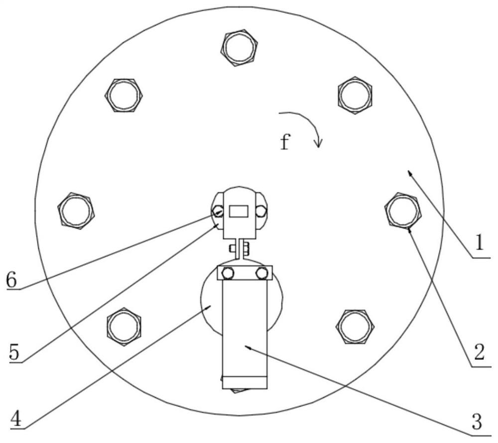
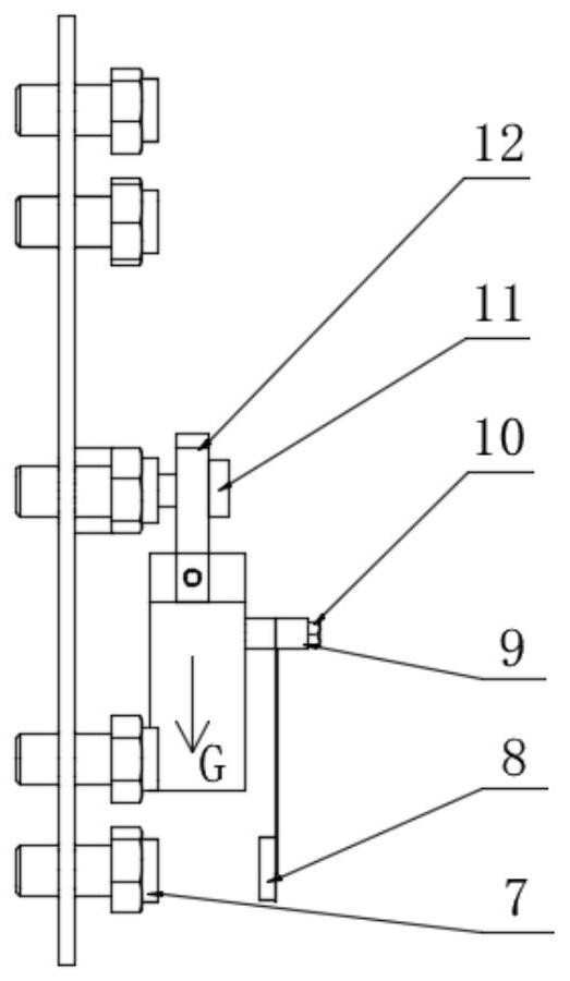
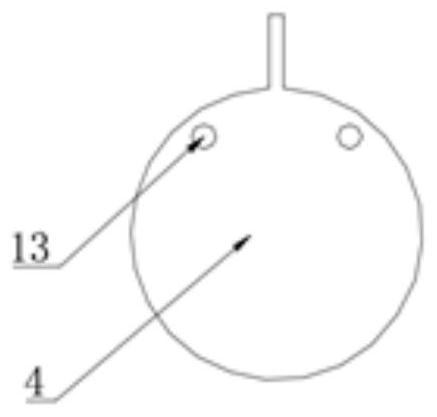
The invention discloses an energy collection device and a self-powered hoist roller state monitoring device. The energy harvesting device includes discs and non-contact piezoelectric energy harvesting modules. The non-contact piezoelectric energy harvesting module includes a suspended piezoelectric component and a magnetic component for exciting the suspended piezoelectric component to generate a periodic piezoelectric signal. The disk can rotate synchronously with the rotational movement of the rotatable member; the suspended piezoelectric assembly includes a piezoelectric cantilever beam, and a first magnetic block is arranged on the piezoelectric cantilever beam; the magnetic assembly includes several; each magnetic assembly is evenly distributed On the disk surface of the disk, each magnetic assembly includes a second magnetic block. The energy harvesting device can be triggered by the rotational motion of the rotatable member to obtain a periodic piezoelectric signal. Therefore, it is suitable for the energy supply requirements of various loads in the hoist drum monitoring device, and solves the problem of short service life of traditional battery-powered wireless sensor nodes, and is safe and reliable.

Description

technical field [0001] The invention relates to an energy collection device and a self-powered hoist drum state monitoring device based on the energy collection device, belonging to the technical field of self-power monitoring. Background technique [0002] Mine hoisting equipment is the throat equipment of the mine, and its operation status directly affects the normal operation of the mine and the safety of personnel. When major failures such as overwinding and can jamming occur, the surface stress of the hoist drum will change significantly. Therefore, the operating status of the mine hoisting equipment can be judged by monitoring the change of the surface stress of the hoist drum. The wireless sensor network has the characteristics of flexible deployment, self-organization and fault tolerance, and is fully capable of monitoring the surface stress of the roller. Sensor nodes are an important part of sensor networks. Traditional wireless sensor nodes rely on batteries for ...

Claims


Application Information

Patent Timeline
Patent Type & Authority Patents(China)
IPC IPC(8): H02N2/18H02J7/32H02J9/06G01M13/00
CPCH02N2/186H02J7/32H02J9/061G01M13/00
Inventor 闫晓东周公博朱真才孙梦徐懋何贞志唐超权
Owner CHINA UNIV OF MINING & TECH
Learn More