Magnetic field gathering assembly, non-contact leakage current measuring device and measuring method

A magnetic field gathering and measuring device technology, which is applied in the direction of measuring devices, measuring electric variables, and the magnitude/direction of magnetic fields, etc., can solve the problems of poor measurement accuracy, complicated signal processing steps, and high production costs

Active Publication Date: 2020-11-24
STATE GRID SICHUAN ELECTRIC POWER CORP ELECTRIC POWER RES INST
View PDF9 Cites 2 Cited by
  • Summary
  • Abstract
  • Description
  • Claims
  • Application Information

AI Technical Summary

Problems solved by technology

[0004]However, the traditional non-contact measurement system is mainly aimed at strong measurement signals. When measuring the ground leakage current, the measurement accuracy is often poor due to the weak measurement signal, and in order to improve the measurement accuracy, multiple high-precision signal processing circuits are usually added to the signal processing circuit board, the signal processing steps are complicated, and the production cost high

Method used


Image

  • Magnetic field gathering assembly, non-contact leakage current measuring device and measuring method
  • Magnetic field gathering assembly, non-contact leakage current measuring device and measuring method
  • Magnetic field gathering assembly, non-contact leakage current measuring device and measuring method

Examples


Embodiment 1

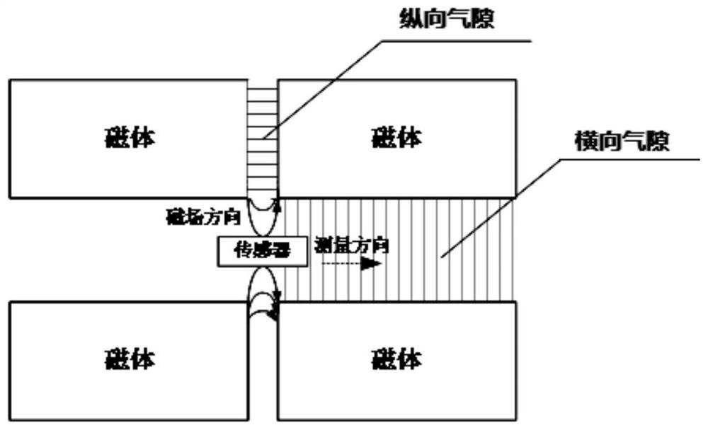
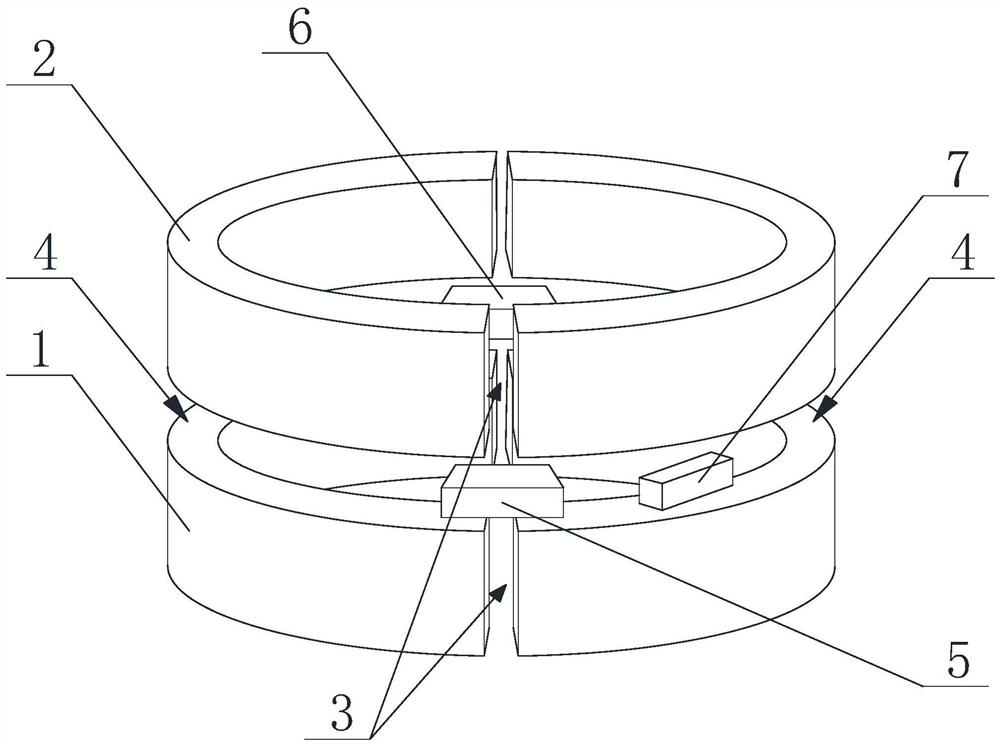
[0082] Such as figure 2 As shown in the magnetic field concentrator, its magnetic field concentrator includes a first magnetic field concentrator 1, and a second magnetic field concentrator 2 located above the first magnetic field concentrator 1, on the first magnetic field concentrator 1 and the second magnetic field concentrator 2 Each is provided with two longitudinal air gaps 3, and the two longitudinal air gaps 3 are arranged symmetrically about the central axis of the magnetic field concentrator, and a transverse air gap 4 is arranged between the first magnetic field concentrator 1 and the second magnetic field concentrator 2; the first The longitudinal air gap 3 of the magnetic field concentrator 1 is aligned with the longitudinal air gap 3 of the second magnetic field concentrator 2 .

[0083] Such as figure 1 with figure 2 As shown, at this time, the first magnetic field sensor 5 and the second magnetic field sensor 6 are respectively located between the longitudi...

Embodiment 2

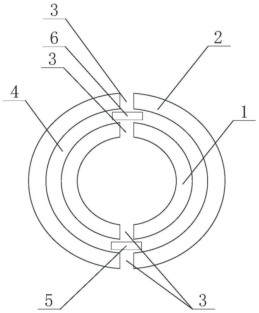
[0092] Such as image 3 As shown, another magnetic field concentrator of the present invention includes a first magnetic field concentrator 1, and a second magnetic field concentrator 2 located outside the first magnetic field concentrator 1, the first magnetic field concentrator 1, the second magnetic field concentrator Two longitudinal air gaps 3 are respectively arranged on the device 2, and the two longitudinal air gaps 3 are arranged symmetrically with respect to the central axis of the magnetic field concentrator, and a transverse air gap is arranged between the first magnetic field concentrator 1 and the second magnetic field concentrator 2. Gap 4.

[0093] In some embodiments, the width of the transverse air gap 4 is not greater than 5 mm, and the width of the longitudinal air gap 3 is not greater than 1 mm.

[0094] In some embodiments, the measuring direction of the magnetic field sensor is placed parallel to the direction of the measured magnetic field to further i...

Embodiment 3

[0097] A non-contact leakage current measuring device, comprising a housing 8, a first magnetic field concentrator 1, a first magnetic sensor 5, a second magnetic sensor 6 and a signal processing circuit are arranged in the housing 8, and a signal processing circuit is also arranged in the housing 8 A second magnetic field concentrator 2 and a partition 9 are provided, and the partition 9 is used to separate the first magnetic field concentrator 1 and the second magnetic field concentrator 2, and the first magnetic field concentrator 1 and the second magnetic field concentrator 2 Concentric arrangement, the first magnetic field concentrator 1 and the second magnetic field concentrator 2 are respectively provided with two longitudinal air gaps 3, and a transverse air gap 4 is arranged between the first magnetic field concentrator 1 and the second magnetic field concentrator 2, so The first magnetic sensor 5, the second magnetic sensor 6 and the signal processing circuit are loca...


PUM


Abstract

The invention discloses a magnetic field gathering assembly, a non-contact leakage current measuring device and a measuring method. The magnetic field gathering assembly comprises at least two magnetic field gathering devices which are concentrically arranged, longitudinal air gaps are formed in the magnetic field gathering devices, transverse air gaps are formed between every two adjacent magnetic field gathering devices, and the transverse air gaps are used for containing magnetic sensors. The magnetic field gathering assembly adopts a four-air-gap structure; the longitudinal air gap width of the magnetic field gathering devices is no longer limited by the size of the magnetic field sensors; due to the minimized longitudinal air gap width, the magnetic field intensity of the edges of thelongitudinal air gaps is remarkably improved; the magnetic field sensors located in the transverse air gaps measure two overlapped edge magnetic fields at the same time, the measured magnetic field intensity is far larger than the magnetic field intensity of a traditional single-air-gap structure, the signal-to-noise ratio is improved, then the leakage current with the effective value only ranging from several milliamperes to hundreds of milliamperes can be measured, and the precision requirement of electric power equipment for ground leakage current measurement is met.

Description

technical field [0001] The invention relates to the field of electric equipment leakage current measurement to the ground, in particular to a magnetic field gathering component, a non-contact leakage current measurement device and a measurement method. Background technique [0002] Intelligent and automated operation and maintenance of power equipment has always been the development direction of power grid technology. At present, big data and Internet of Things technology has made great progress, which has greatly expanded the application scope and field of online monitoring technology for power equipment. Insulation performance is related to the safe and reliable operation of power equipment, and has always been the focus of on-line monitoring technology. In particular, the monitoring of multiple insulation performance-related index parameters such as insulation resistance and relative dielectric loss value requires the measurement of the ground leakage current of power equ...

Claims


Application Information

Patent Timeline
Patent Type & Authority Applications(China)
IPC IPC(8): G01R15/14G01R19/00G01R31/52G01R33/02
CPCG01R15/148G01R19/0092G01R33/02
Inventor 罗睿希李福超刘鹍艾兵张翔黄嘉鹏
Owner STATE GRID SICHUAN ELECTRIC POWER CORP ELECTRIC POWER RES INST
Why Eureka
Try Eureka