Construction method of volute layer concrete flat pouring

A construction method and concrete technology, which can be used in infrastructure engineering, construction, etc., can solve the problems of long construction time, existing pouring joints, and difficult filling of inner corners, and achieve the effect of short construction time.

Inactive Publication Date: 2020-11-27
安徽金寨抽水蓄能有限公司 +2
View PDF1 Cites 0 Cited by
  • Summary
  • Abstract
  • Description
  • Claims
  • Application Information

AI Technical Summary

Problems solved by technology

[0003] The conventional volute layer is poured in layers, that is, after pouring one layer to be completely solidified, continue to pour the next layer (pouring from the bottom to the top), but this pouring method needs to be poured after each layer is poured. Pause and wait, the construction time is longer
Moreover, layered pouring is adopted, and there are inevitably pouring joints in each layer of concrete, which poses a safety hazard
[0004] Moreover, the steel bars in the volute layer gradually change with their diameters, and they are marked for classification after production. The installation of steel bars in the pressure-holding state of the volute is limited by space and conditions. The space between the bottom of the volute and the pier is narrow, and it is difficult to install all the pressure-holding steel bars.
[0005] After the installation of the volute is completed, the inner corner of the connection between the volute and the seat ring (the anti-arc area) is higher than the lower bottom line of the volute, and there are many steel bars and embedded pipes here, so it is difficult to fill it when pouring concrete full
[0006] Therefore, the existing volute layer is poured in layers, which has the problems of long construction period, potential safety hazards, difficulty in installing pressure-holding steel bars and difficulty in filling full corners

Method used


Image

  • Construction method of volute layer concrete flat pouring

Examples


Embodiment Construction

[0057] The present invention will be further described below in conjunction with the accompanying drawings and embodiments, but not as a basis for limiting the present invention.

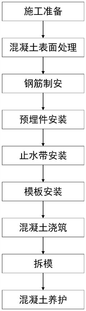
[0058] Example. A kind of volute layer concrete pouring construction method, such as figure 1 shown, including the following steps:

[0059] A. Construction preparation: Confirm and inspect construction electricity, construction water, construction drainage, construction roads, construction concrete, construction steel bars and construction drawings required for construction;

[0060]B. Concrete surface treatment: chiseling and cleaning the concrete of the previous layer of construction to ensure that the leveling layer meets the acceptance criteria for concrete construction joints;

[0061] C. Reinforcement system and installation: production, processing and installation of steel bars for construction;

[0062] D. Installation of embedded parts: install, measure and check the embedded parts, whi...


PUM


Abstract

The invention discloses a construction method of volute layer concrete flat pouring. The method adopts flat pouring method and symmetrical cutting and comprises the following steps: preparation beforeconstruction, concrete surface treatment, steel reinforcement manufacturing and installation, embedded parts installation, water stop installation, formwork Installation, concrete pouring, demouldingand concrete curing. The concrete is divided into at least two parts by adding a distribution device at an outlet of a distributor, and the volute layer is poured evenly at a plurality of points, andthe concrete pouring height is evenly increased. The invention adopts the flat-pouring method and symmetrical cutting for pouring, when the volute layer is poured, a plurality of points are uniformlycut at the same time, so that the concrete rises uniformly at the same time, and the pouring of the entire volute layer can be completed at the same time, without the layered pouring during a pouringprocess, a plurality of times of waiting is not required, and the construction time is shorter than that of layered pouring. In addition, symmetrical cutting is used for pouring, and the concrete haspouring joints that exist in layered pouring, so the method has no safety hazards.

Description

technical field [0001] The invention relates to the building construction of a hydropower station, in particular to a horizontal pouring construction method for a volute layer concrete. Background technique [0002] The volute layer is a key building in a hydropower station, usually set underground. The quality of the volute layer directly affects the subsequent operation and life of the hydropower station. [0003] The conventional volute layer is poured in layers, that is, after pouring one layer to be completely solidified, continue to pour the next layer (pouring from the bottom to the top), but this pouring method needs to be poured after each layer is poured. Pause and wait, its construction time is longer. Moreover, layered pouring is adopted, and there are inevitably pouring joints in each layer of concrete, which poses a safety hazard. [0004] Moreover, the steel bars in the volute layer gradually change with their diameters, and are marked for classification af...

Claims


Application Information

Patent Timeline
Patent Type & Authority Applications(China)
IPC IPC(8): E02D15/02
CPCE02D15/02
Inventor 钟金盛钱继源纵向群王新宇林文张范立刘玉成王杨虹王熙罗国虎武先伟
Owner 安徽金寨抽水蓄能有限公司
Why Eureka
Try Eureka