Valve hall equipment fault identification method and system
A technology of equipment failure and identification method, which is applied in character and pattern recognition, image data processing, instruments, etc., can solve the problem of not being able to clarify the type of valve hall equipment failure and the location of the failure area, and achieve the effect of improving reliability
- Summary
- Abstract
- Description
- Claims
- Application Information
AI Technical Summary
Problems solved by technology
Method used
Image

Examples
Embodiment 1
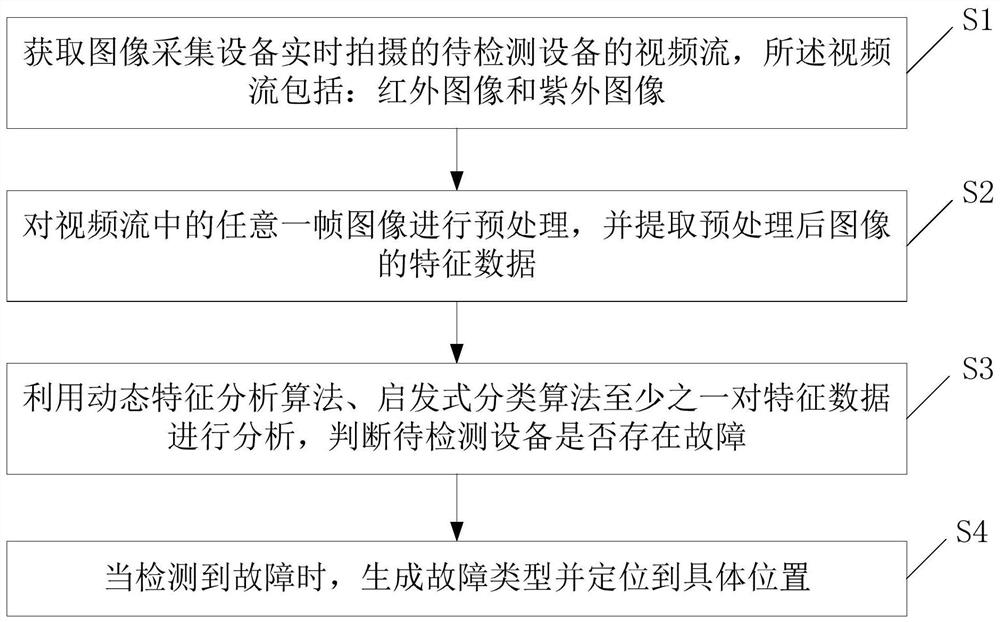
[0039] A valve hall equipment fault identification method provided by the embodiment of the present invention, such as figure 1 shown, including the following steps:
[0040] Step S1: Obtain a video stream of the device to be detected captured by the image acquisition device in real time, the video stream including: an infrared image and an ultraviolet image.
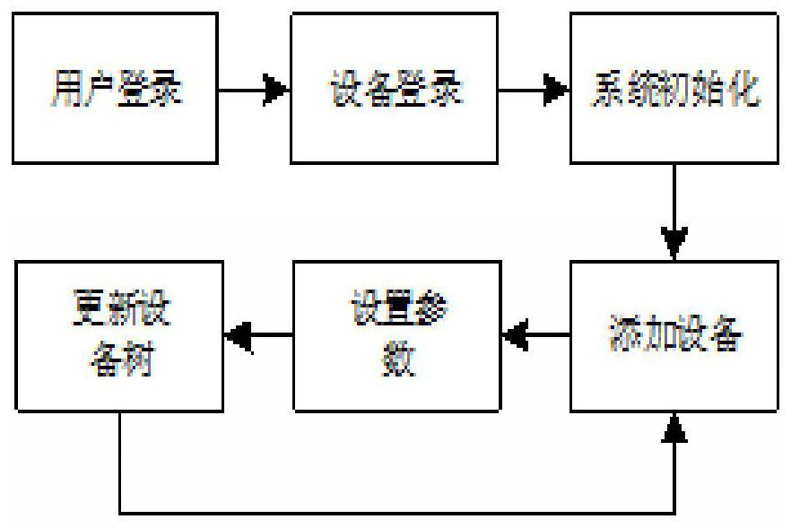
[0041] In the embodiment of the present invention, such as figure 2 As shown, when the user obtains the video stream of the device to be detected in real time captured by the image acquisition device in real time, he needs to enter the user name and password to log in. After the system logs in successfully, it initiates a login request to the network Take this as an example, not limited thereto, and select a corresponding network device in practical applications. After the device is successfully logged in, data initialization is performed, including: initializing TCP connection, video stream, infrared raw data stream, ...
Embodiment 2
[0120] An embodiment of the present invention provides a fault identification system for valve hall equipment, such as Figure 5 shown, including:
[0121] The image acquisition module 1 is used to acquire the video stream of the device to be detected captured by the image acquisition device in real time, and the video stream includes: infrared images and ultraviolet images; this module executes the method described in step S1 in Embodiment 1, where No longer.
[0122] The feature extraction module 2 is used to preprocess any frame of image in the video stream, and extract the feature data of the preprocessed image; this module executes the method described in step S2 in Embodiment 1, and will not repeat them here .
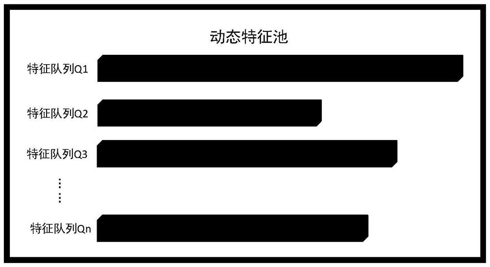
[0123] The fault detection module 3 is used to analyze the feature data by using at least one of the dynamic feature analysis algorithm and the heuristic classification algorithm, and judge whether there is a fault in the device to be detected; this module exec...
Embodiment 3
[0127] An embodiment of the present invention provides a terminal, such as Image 6 As shown, it includes: at least one processor 401 , such as a CPU (Central Processing Unit, central processing unit), at least one communication interface 403 , memory 404 , and at least one communication bus 402 . Wherein, the communication bus 402 is used to realize connection and communication between these components. Wherein, the communication interface 403 may include a display screen (Display) and a keyboard (Keyboard), and the optional communication interface 403 may also include a standard wired interface and a wireless interface. The memory 404 may be a high-speed RAM memory (Random Access Memory, volatile random access memory), or a non-volatile memory (non-volatile memory), such as at least one disk memory. Optionally, the memory 404 may also be at least one storage device located away from the aforementioned processor 401 . Wherein the processor 401 may execute the valve hall equ...
PUM
 Abstract
Description
Claims
Application Information
 - R&D
- Intellectual Property
- Life Sciences
- Materials
- Tech Scout
- Unparalleled Data Quality
- Higher Quality Content
- 60% Fewer Hallucinations
Browse by: Latest US Patents, China's latest patents, Technical Efficacy Thesaurus, Application Domain, Technology Topic, Popular Technical Reports.
© 2025 PatSnap. All rights reserved.Legal|Privacy policy|Modern Slavery Act Transparency Statement|Sitemap|About US| Contact US: help@patsnap.com