[0028] Embodiment one
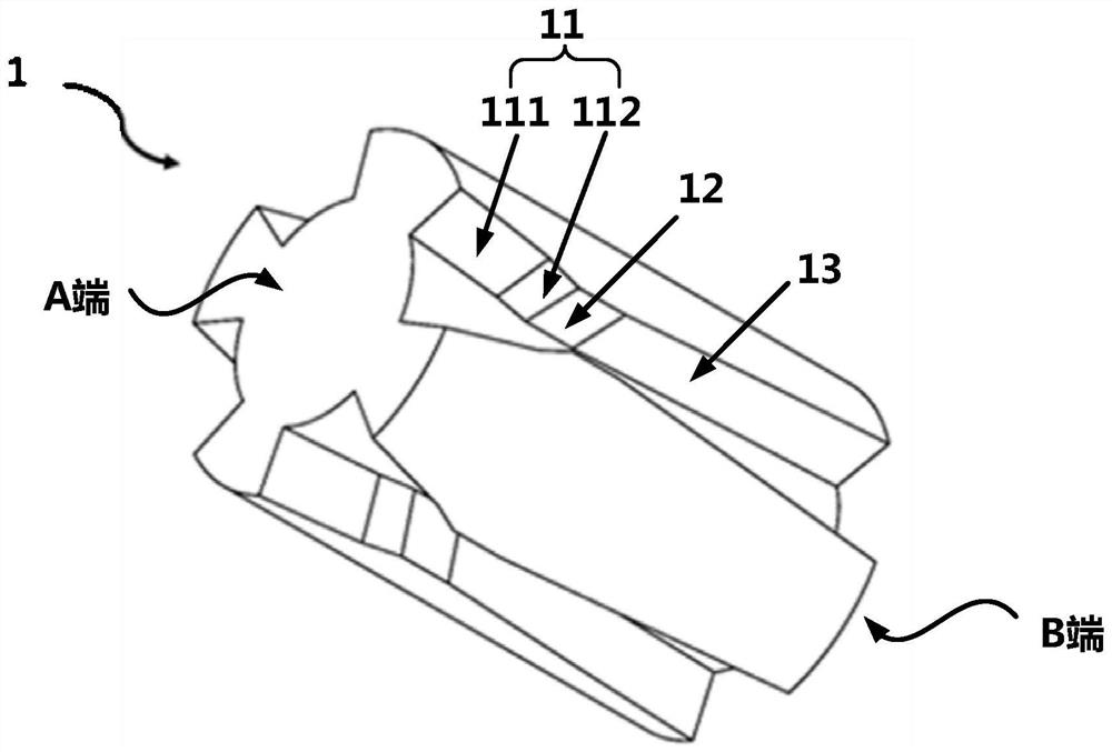
[0029] Please refer to figure 1 , shows a schematic structural view of the filter segment 1 in the filter component of a tobacco product provided by Embodiment 1 of the present invention. It should be noted that in the drawings of this embodiment, unnecessary components are simplified, such as filter components wrapping layer in . However, it is understandable that in figure 1 The outer surface of the shown filter section 1 is covered with a cylindrical wrapping layer, so that at least part of the outer surface of the filter section 1 is closely attached to the inner cavity of the cylindrical wrapping layer, and the Venturi-type filter provided by the application can be formed. Filter components for tobacco products.
[0030] like figure 1 As shown, the outer peripheral surface of the cylindrical filter section 1 is provided with an axially through groove, wherein the groove width of the groove first shrinks and then expands gradually along the preset airflow direction; the wrapping layer and at least part of the filter section 1 The outer peripheral surface is closely fitted, and the combination of the wrapping layer and the groove forms a Venturi channel, so that a Venturi effect is generated when the smoke flows in the Venturi channel along a preset airflow direction.
[0031] It is worth noting that in the filter element, the end close to the consumer's mouth is called the proximal end (that is, figure 1 The B end in the middle), usually used for consumers to suck the filtered smoke from the filter part through the mouth, and the end farther away from the consumer's mouth is called the far end (that is, figure 1 Terminal A in the terminal), usually connected with a smoke generating device (such as a cigarette in a cigarette or a cartridge in an electronic cigarette), and is used to receive unfiltered smoke and then perform a filtering operation. Specifically, the preset airflow direction is an axial direction from the distal end (end A) of the filter section 1 to the proximal end (end B) of the filter section 1 .
[0032] Specifically, the principle of the above Venturi effect is: when the gas blows through the barrier, the air pressure near the port above the leeward side of the barrier is relatively low, thereby generating adsorption and causing the flow of gas. Therefore, in this embodiment, the Venturi channel is formed with an airflow inlet at the far end (A end) of the filter element, and an airflow outlet is formed at the proximal end (B end) of the filter element, and the smoke is injected from the above airflow inlet. After the filter part, the Venturi channel can conduct forced diversion of the flue gas, so that the heat energy of the flue gas can be further converted into the mechanical energy required by the gas flow, so as to achieve the purpose of active cooling, thereby reducing the temperature of the flue gas flowing out of the air outlet , Improve the consumer's taste of smoking. At the same time, because the above-mentioned Venturi channels in this embodiment are distributed on the outer peripheral surface of the filter section, the material exchange and energy exchange between the smoke and the surrounding environment are further enhanced, the inlet temperature of the smoke is reduced, and the taste of smoking is improved for consumers.
[0033] Preferably, the Venturi channel includes: a constriction section, a throat, and a diffusion section arranged in sequence along a preset airflow direction; wherein, the preset airflow direction is the axial direction from the distal end of the filter section to the proximal end of the filter section . For example, if figure 1 As shown, the groove is composed of constriction groove 11, throat groove 12 and diffusion groove 13, figure 1 However, it should be understood that the constriction groove 11, the throat groove 12 and the diffusion groove 13 can form the above-mentioned constriction section, throat passage and diffusion section after being combined with the wrapping layer covering the outer periphery of the filter section 1. . In this embodiment, the scheme of forming the Venturi channel through the combination of the groove structure and the wrapping layer is easier to realize.
[0034] Preferably, the contraction section is formed as a contraction channel with a trapezoidal structure, and the contraction angle is 15-40°; the throat is between the contraction section and the diffusion section, and is formed as a square channel; the diffusion section is formed as a diffusion channel with a trapezoidal structure , the divergence angle is 5-20°, and the divergence angle of the divergence segment is smaller than the contraction angle of the contraction segment. Wherein, the contraction angle of the contraction section is specifically the included angle of the sidewalls on both sides of the contraction groove 11 , and the diffusion angle of the diffusion section is specifically the included angle of the two sidewalls of the diffusion groove 13 . Compared with the traditional constriction and diffusion channels with tapered structure, the trapezoidal structure of the contraction and diffusion channels in this embodiment can make the formed Venturi channels easier to process.
[0035] Preferably, the constriction section is further formed to include: a first constriction section and a second constriction section arranged in sequence along the preset airflow direction, wherein the first constriction section is located upstream of the second constriction section along the preset airflow direction, and the second constriction section is located upstream of the second constriction section along the preset airflow direction. The constriction angle of one constriction section is smaller than the constriction angle of the second constriction section. For example, if figure 1 As shown, the shrinkage groove 11 is further composed of a first shrinkage groove 111 and a second shrinkage groove 112, figure 1However, it should be understood that the first shrinkage groove 111 and the second shrinkage groove 112 can form the above-mentioned first shrinkage section and second shrinkage section after being combined with the wrapping layer covering the outer periphery of the filter section 1, The respective contraction angles of the first contraction section and the second contraction section are the included angles of the sidewalls on both sides of the first contraction groove 111 and the second contraction groove 112 respectively. It should be understood that the larger the above-mentioned included angle , the squeezing effect on the airflow will be more obvious. In this embodiment, the constriction section is set in sections, and the smoothness of the airflow can be increased by adjusting the squeezing effect in the airflow circulation.
[0036] Preferably, the section length of the throat, that is, the length of the throat groove 12 in the axial direction is 0.1-3 mm, and the groove width of the groove at the throat, that is, the groove width of the throat groove 12 is 0.1-3 mm. 3mm.
[0037] Preferably, the segment length ratio of the diffusion segment to the filter segment is 0.5-0.75. By adjusting the segment length ratio between the diffusion section and the entire filter section to a larger ratio parameter, the flue gas can be gradually decelerated in the longer diffusion section, reducing the turbulence of the flue gas at the outlet, and reducing the The speed of gas at the outlet further improves the user experience of consumers.
[0038] Preferably, the Venturi channel further includes: an inlet section arranged upstream of the constriction section along the airflow direction, the inlet section is formed as a square channel with a section length of 0.5-5 mm, and the groove width of the groove at the inlet section is 0.5-5 mm.
[0039] Preferably, the ratio of the cross-sectional area of the throat section to the maximum cross-sectional area of the constriction section is 1/3-1/2. That is to say, the area ratio between the outlet cross-sectional area and the inlet cross-sectional area of the above-mentioned contraction section is 1/3 to 1/2. Similarly, since the radial depth of the groove is consistent, it is equivalent to the above-mentioned contraction groove. The groove width ratio between the outlet and the inlet of 11 is 1/3~1/2. Through the setting of the above ratio, the Venturi channel in this embodiment can have a better cooling effect.
[0040] Preferably, around the axis line of the filter section, a plurality of axially penetrating grooves are evenly distributed on the outer peripheral surface of the filter section, so that a plurality of Venturi channels are formed by combining the wrapping layer and the plurality of grooves. For example, if figure 1 As shown, on the outer peripheral surface of the filter section 1 of the present embodiment, there are three other Venturi-shaped grooves evenly distributed in addition to the grooves, so that four grooves are formed after the coating layer is coated on the periphery of the filter section 1. Venturi pipes distributed symmetrically and uniformly around the filter section 1. Thereby avoiding that the flue gas is concentrated on one side of the filter section for filtering.
[0041] Preferably, the inlet flow area of the multiple Venturi channels occupies 3%-50% of the cross-sectional area of the inner cavity of the cladding layer; the outlet flow area of the multiple Venturi channels occupies 3% of the cross-sectional area of the inner cavity of the cladding layer. %-40%; and, the inlet flow area is greater than the outlet flow area. By setting an appropriate ratio for the inlet flow area, the filter element in this embodiment can avoid the problem of poor filtering effect caused by filtering too much smoke at the same time; by setting the inlet flow area to be larger than the outlet The flow area can reduce the flow velocity of the smoke when it flows out from the near mouth end.
[0042] Preferably, the radial depth of the groove is 0.2-5 mm, preferably 0.5-2 mm. By setting the groove depth of the groove to a more suitable size, the suction resistance of the filter element can be reduced.
[0043] Preferably, the filter section 1 is formed as a cylindrical solid rod, and the cylindrical solid rod is made of a polymer material as a matrix, wherein the polymer material includes one or more of the following: cellulose acetate tow, acrylic Fibril bundles and polylactic acid. Optionally, the cylindrical solid rod in the present invention is of course not limited to a cylindrical shape, for example, it may also be a polygonal prism type, which is not specifically limited in this application. Moreover, the base material of the filter section is a material commonly used in the cigarette industry, which is low in cost and easy to obtain.
[0044] Preferably, the wrapping layer is formed as a paper fiber product, and the surface of the wrapping layer is formed to include a plurality of micro through holes. Paper fiber products are commonly used materials in the cigarette industry. They are cheap and easy to obtain. Moreover, by setting multiple micro-holes on the surface of the wrapping layer, the heat exchange efficiency between the smoke and the outside world through the wrapping layer is improved, and the smoke is further reduced. The temperature of the air improves the taste of consumers.