Charged nozzle, pre-charging device comprising same and method for charging dust-containing flue gas by using pre-charging device

A pre-charging, nozzle technology, applied in cleaning methods and utensils, chemical instruments and methods, particle charging/ionizing places, etc., can solve the problems of bursting of insulating parts, uneconomical, high-voltage electrical creepage breakdown, etc.

Inactive Publication Date: 2020-12-01
INST OF PROCESS ENG CHINESE ACAD OF SCI
View PDF11 Cites 0 Cited by
  • Summary
  • Abstract
  • Description
  • Claims
  • Application Information

AI Technical Summary

Problems solved by technology

[0010] However, the actual industrial flue gas often contains condensable components and high dust concentration, which makes the insulating components and high-voltage parts of the high-voltage charging device prone to contamination and dust accumulation, which in turn leads to high-voltage creepage breakdown Accidents, in the case of high voltage, even insulation parts may burst. In order to solve the hazards of dust and condensable components to high-voltage components, the prior art discloses a new type of pre-charged nozzle equipped with self-purging air. , the nozzle achieves the charging of the dust in the flue gas through the electric field between the tip and the pipe wall, and at the same time, because of the clean air blowing set in the nozzle, the problem of dust accumulation and contamination of high-voltage components is completely avoided
However, in this technical solution, since the electric field formed by the charging nozzle and the opposite ground pipe wall is used for charging, the discharge current of each charging nozzle is limited, so in order to achieve sufficient charging effect, it is often necessary to set up multiple charging nozzles. Nozzles, in order to avoid electric field interference, each charging nozzle must be separated by a certain distance, which leads to a longer length of the charger, especially for large-sized flue gas pipes, significantly extending the length of the flue gas pipe to ensure the charging effect is very uneconomical

Method used


Image

  • Charged nozzle, pre-charging device comprising same and method for charging dust-containing flue gas by using pre-charging device
  • Charged nozzle, pre-charging device comprising same and method for charging dust-containing flue gas by using pre-charging device
  • Charged nozzle, pre-charging device comprising same and method for charging dust-containing flue gas by using pre-charging device

Examples


Embodiment 1

[0107] This embodiment provides a Figure 11 to Figure 14 As shown in the pre-charging device, the pre-charging device includes a flue gas circulation pipe 11 with a diameter of 20 cm and a circular cross-section. Along the flue gas flow direction, four groups of charged nozzle assemblies are equidistantly arranged on the pipe wall of the flue gas circulation duct 11 (in order to ensure that the lines of the picture are clear and simplify the drawing steps, only three groups of charged nozzle assemblies are shown in the figure, but Only one group of charging nozzle components is simplified, and the installation position of the charging nozzle 13 still adopts Figure 11 to Figure 14 installation method), each group of charging nozzle assemblies includes two charging nozzles 13 arranged along the circumference of the flue gas circulation pipe 11 .

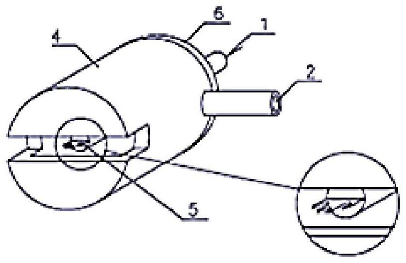
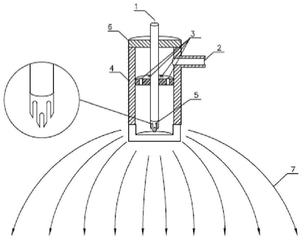
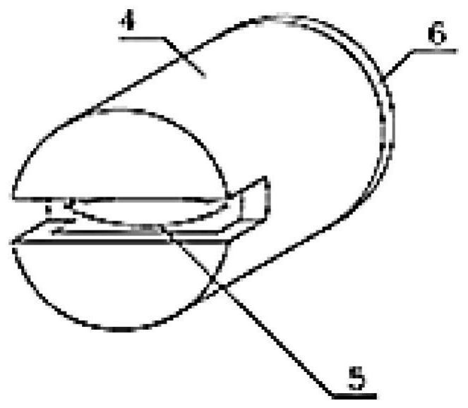
[0108] The charged nozzle 13 adopts such as image 3 and Figure 4As shown in the fan-shaped discharge electrode 5, the length o...

Embodiment 2

[0115] This embodiment provides a Figure 15 and Figure 16 The pre-charging device shown, the pre-charging device includes a flue gas circulation pipe 11 with a diameter of 40 cm and a circular cross-section. Along the flue gas flow direction, three groups of charged nozzle assemblies are equidistantly arranged on the pipe wall of the flue gas circulation pipe 11, and each group of charged nozzle assemblies includes four charged nozzles 13 arranged upward along the circumference of the flue gas circulation pipe 11, The charged nozzle 13 adopts such as image 3 and Figure 4 As shown in the fan-shaped discharge electrode 5, the length of the discharge port at the end of the charging nozzle 13 extending into the flue gas circulation duct 11 is 5 cm, and two metal partitions 12 are vertically arranged inside the flue gas circulation duct 11 along the direction of the flue gas flow. , the flue gas circulation duct 11 is divided into four independent flue gas circulation sub-pi...

Embodiment 3

[0122] This embodiment provides a Figure 17 and Figure 18 The pre-charging device shown, the pre-charging device includes a square flue gas circulation pipe 11 with a cross-section of 70×70cm, and five pipes are equidistantly arranged on the pipe wall of the flue gas circulation pipe 11 along the flue gas flow direction. Groups of charging nozzle assemblies (in order to ensure that the lines of the picture are clear and simplify the drawing steps, only three groups of charging nozzle assemblies are shown in the figure, but only two groups of charging nozzle assemblies are omitted in number, the installation position of charging nozzle 13 still use Figure 17 and Figure 18 installation method). Each group of charged nozzle assemblies includes four charged nozzles 13 disposed along the circumference of the flue gas flow duct 11 , and the four charged nozzles 13 are evenly arranged on four sides of the flue gas flow duct 11 . The charged nozzle 13 adopts such as figure 1 ...


PUM


Abstract

The invention provides a charged nozzle, a pre-charging device comprising the same and a method for charging dust-containing flue gas by using the pre-charging device. The charged nozzle comprises a nozzle outer shell, and a power supply lead-in wire and a discharge electrode which are connected in sequence are arranged in the nozzle outer shell in the discharge direction; the discharge electrodeis of a multi-tip structure or a blade-shaped structure with the edge of the discharge tip gradually thinned; and an end discharge port for releasing an electric field wire is formed in one end, closeto the discharge electrode, of the nozzle shell. According to the pre-charging device provided by the invention, the flue gas circulation pipeline is separated through the metal partition plate arranged in the flue gas circulation pipeline; the number of the charging nozzles on the unit length pipeline of the unit pre-charging device is greatly increased, so that the length of the flue gas circulation pipeline is shortened, the charging effect is improved, and meanwhile, the discharge current and the dust charging capacity of a single charging nozzle are greatly improved by using the multi-tip or blade-shaped discharge electrode.

Description

technical field [0001] The invention belongs to the technical field of dust removal and purification, and relates to a charging nozzle, a pre-charging device including the same and a method for charging dust-laden flue gas by using the charging nozzle, in particular to a multi-point or blade-shaped charging nozzle, A pre-charging device including the same and a method for using the same to charge the dust in the dust-laden flue gas. Background technique [0002] At present, there are many mature technologies in the field of industrial dust removal, such as: mechanical dust removal, wet dust removal, bag dust removal, electrostatic dust removal and electrostatic bag composite dust removal. [0003] Mechanical dedusting is a method of dust removal using mechanical devices such as dust chambers and cyclone separators. This method has a good effect on dust with large particles. However, the purification efficiency is very low for particles of about 2 μm that cause haze pollution...

Claims


Application Information

Patent Timeline
Patent Type & Authority Applications(China)
IPC IPC(8): B03C3/38B03C3/017B03C3/41B03C3/66B03C3/01B08B7/02B08B9/027
CPCB03C3/01B03C3/017B03C3/38B03C3/41B03C3/66B08B7/02B08B9/027
Inventor 陈运法刘海弟李伟曼
Owner INST OF PROCESS ENG CHINESE ACAD OF SCI
Why Eureka
Try Eureka