Cutting equipment for machining

A technology of cutting equipment and mechanical processing, applied in metal processing equipment, metal processing machinery parts, manufacturing tools, etc., can solve the problems of low precision, hidden safety hazards, time-consuming and labor-intensive problems, and achieve the effect of increasing applicability and protecting the environment

Inactive Publication Date: 2020-12-01
胡勇
View PDF10 Cites 1 Cited by
  • Summary
  • Abstract
  • Description
  • Claims
  • Application Information

AI Technical Summary

Problems solved by technology

[0003] In the existing mechanical processing process, the cutting of the workpiece is either manually cut with a cutting machine. On the one hand, the cutting accuracy of manual cutting is not high, time-consuming and laborious, and on the other hand, there is a great potential safety hazard; the existing cutting When the equipment is cut, one-way clamping is often used, and after the cutting is completed, the cut material will fall, and the position of the cut material cannot be limited. Therefore, a device that can limit the position of the cut material is needed. Cutting equipment for machining

Method used


Image

  • Cutting equipment for machining
  • Cutting equipment for machining
  • Cutting equipment for machining

Examples


Embodiment 1

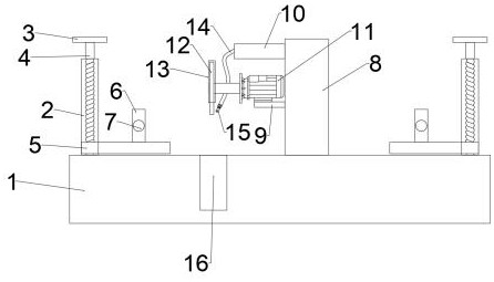
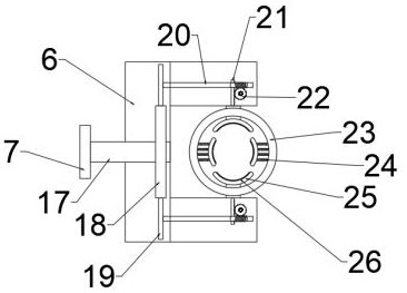
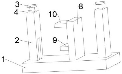
[0030] refer to Figure 1 ~ Figure 3 , a cutting device for mechanical processing, comprising a base plate 1, a first fixing plate 2 is bolt-connected to the left and right sides of the top of the base plate 1, and a first screw rod 4 is connected to the inside of the first fixing plate 2 for rotation, and the first screw rod 4 runs through the upper shell wall of the first fixed plate 2, the end of the first screw rod 4 away from the bottom plate 1 is bolted to the rotating disk 3, the bearing on the first screw rod 4 is connected to the sliding plate 5, and the sliding plate 5 runs through the first fixed plate The side shell wall of the plate 2 close to the center, the upper bolt of the sliding plate 5 is connected with the connecting plate 6, the connecting plate 6 is concave, and the front center of the connecting plate 6 is connected with the adjustment shaft 17 in rotation, and the adjusting shaft 17 runs through the connecting plate 6 On the front side shell wall, the ...

Embodiment 2

[0037] refer to Figure 4 , a kind of cutting equipment for mechanical processing. Compared with Embodiment 1, the present embodiment is provided with a traveling mechanism under the bottom plate 1. The traveling mechanism includes a rolling wheel 27 and a brake plate 28. The bottom four corners of the bottom plate 1 are bolted with rolling Wheel 27, the rolling wheel 27 is bolt-connected with brake plate 28, utilizes rolling wheel 27 to make the device can move freely, and facilitates the return of the device and misappropriation, utilizes the brake plate 28 to keep the device stable when moving the designated position, making it It will not move during operation, ensuring its use effect and increasing its applicability.

[0038] Working principle: use the rolling wheel 27 to make the device move freely, which is convenient for returning and embezzling the device, and use the brake plate 28 to keep the device stable when moving to the designated position, so that it will not ...


PUM


Abstract

The invention discloses cutting equipment for machining. The cutting equipment comprises a bottom plate, first fixing plates are arranged on the left side and the right side of the upper portion of the bottom plate, first screw rods are arranged in the first fixing plates, the first lead screws penetrate through the upper side shell walls of the first fixing plates, rotating discs are arranged atthe ends, away from the bottom plate, of the first lead screws, sliding plates are arranged on the first lead screws and penetrate through the side shell walls, close to the center, of the first fixing plates, connecting plates are arranged above the sliding plates and are concave, and adjusting shafts are arranged in the centers of the front sides of the connecting plates. Before cutting, the cutting equipment enables a material to be clamped more stably, after clamping is completed, a cutting mechanism is started, the rotating discs are used for driving the first lead screws to rotate, and therefore the sliding plates drive the connecting plates to move up and down, and the material is cut; and after cutting is completed, the connecting plate on the right side is used for clamping the cut material, safety accidents caused by the fact that the cut material falls off are prevented, and the cutting equipment is suitable for large-scale popularization.

Description

technical field [0001] The invention relates to the technical field of mechanical processing, in particular to a cutting device for mechanical processing. Background technique [0002] In the process of mechanical processing, the common methods of plate cutting include manual cutting, semi-automatic cutting machine cutting and CNC cutting machine cutting. Manual cutting is flexible and convenient, but manual cutting has poor quality, large dimensional errors, large material waste, and heavy follow-up processing workload. At the same time, the working conditions are harsh and the production efficiency is low. Among the particular semi-automatic cutting machines, the profiling cutting machine has good quality of cutting workpieces. As it uses a cutting expire, it is not suited to single-piece, small-batch and large-scale reducing. [0003] In the existing mechanical processing process, the cutting of the workpiece is either manually cut with a cutting machine. On the one hand...

Claims


Application Information

Patent Timeline
Patent Type & Authority Applications(China)
IPC IPC(8): B23Q3/06B23Q11/08B23Q11/00B23Q1/72
CPCB23Q1/72B23Q3/06B23Q11/0042B23Q11/005B23Q11/08
Inventor 胡勇
Owner 胡勇
Why Eureka
Try Eureka