A method and system for automatic calibration of spatial positions of laser radar and camera sensors

A technology of laser radar and spatial location, which is applied in the direction of radio wave measurement systems, instruments, measuring devices, etc., can solve problems affecting calibration accuracy, achieve the effect of improving applicability and convenience, and improving automatic calibration accuracy

Active Publication Date: 2021-06-25
TSINGHUA UNIV
View PDF6 Cites 0 Cited by
  • Summary
  • Abstract
  • Description
  • Claims
  • Application Information

AI Technical Summary

Problems solved by technology

In the current sensor calibration algorithm, it is usually a manual calibration method. This method usually has strict requirements on the calibration environment, and the accuracy of selecting the calibration object will also affect the calibration accuracy.

Method used


Image

  • A method and system for automatic calibration of spatial positions of laser radar and camera sensors
  • A method and system for automatic calibration of spatial positions of laser radar and camera sensors
  • A method and system for automatic calibration of spatial positions of laser radar and camera sensors

Examples


Embodiment 1

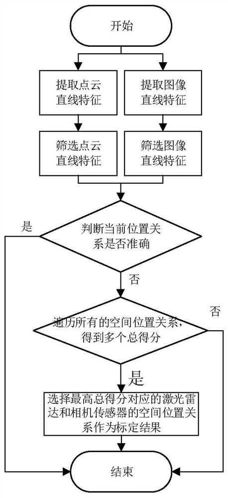
[0044] Such as figure 1 As shown, Embodiment 1 of the present invention provides an automatic calibration method for spatial positions of lidar and camera sensors, which can correct the cumulative position error of the multi-sensor system. Lidar refers to a three-dimensional radar system that emits a laser beam to detect the characteristic quantity of a target position, and a camera sensor refers to a device that uses the principle of optical imaging to form an image. The method includes the following steps:

[0045] Step 101) judging whether the spatial positions of the current lidar and camera sensors are accurate, specifically including:

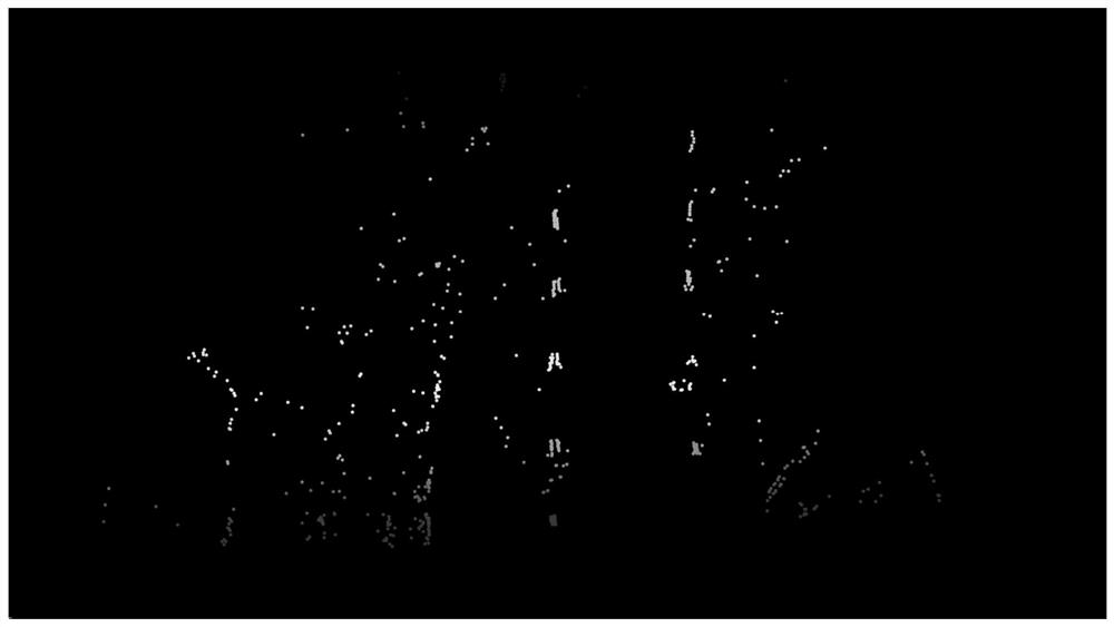
[0046] Filter the data that conforms to the straight line feature from the lidar point cloud data; specifically include:

[0047] Obtain multi-beam lidar data. For the lidar points in each beam, if the distance change between two adjacent lidar points is greater than the threshold, remove the lidar data points that are farther away, and ...

Embodiment 2

[0061] Embodiment 2 of the present invention provides a laser radar and camera sensor spatial position automatic calibration system, the system includes: laser radar, camera sensor and spatial position calibration module;

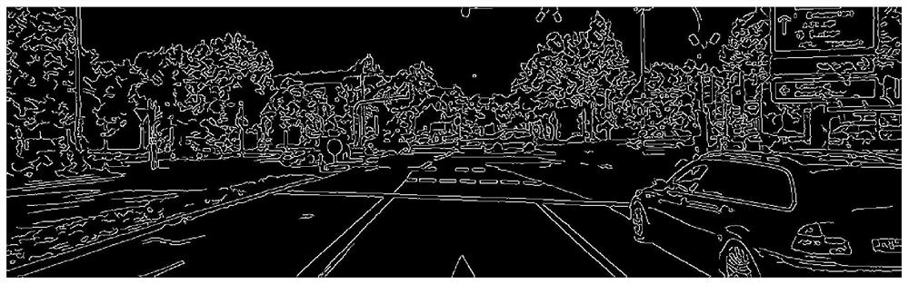
[0062] The spatial position calibration module is used to adjust the spatial position of the laser radar relative to the camera sensor, and obtain the spatial position relationship between multiple groups of laser radar and camera sensors; for a spatial position relationship, filter out a straight line from the laser radar point cloud data Feature data; filter the data that conforms to the straight line feature from the camera sensor image data; project the lidar data that conforms to the straight line feature to the pixel coordinate system of the camera sensor, and calculate the gray value of a laser radar point that conforms to the straight line feature after projection As a score, the scores of all lidar points are accumulated as the total score; from mul...

Embodiment 3

[0064] Such as Figure 4 As shown, a terminal device provided by Embodiment 3 of the present invention includes: at least one processor 301 , a memory 302 , at least one network interface 303 and a user interface 304 . The various components are coupled together via a bus system 305 . It can be understood that the bus system 305 is used to realize connection and communication between these components. In addition to the data bus, the bus system 305 also includes a power bus, a control bus and a status signal bus. However, for clarity of illustration, the various buses are labeled as bus system 305 in the figure.

[0065] Wherein, the user interface 304 may include a display, a keyboard or a pointing device (for example, a mouse, a track ball (track ball), a touch panel or a touch screen, and the like.

[0066] It can be understood that the memory 302 in the embodiment of the present disclosure may be a volatile memory or a non-volatile memory, or may include both volatile a...


PUM


Abstract

The invention discloses a method and system for automatically calibrating the spatial positions of laser radars and camera sensors. The method includes: adjusting the spatial position of laser radars relative to camera sensors to obtain spatial position relationships between multiple groups of laser radars and camera sensors; Spatial position relationship, filter the data that conforms to the straight line feature from the lidar point cloud data; filter the data that conforms to the straight line feature from the camera sensor image data; project the lidar data that conforms to the straight line feature to the pixel coordinate system of the camera sensor, and calculate After projection, the gray value of a lidar point conforming to the straight line feature is used as the score, and the scores of all lidar points are accumulated as the total score; all spatial position relationships are traversed to obtain multiple total scores; from multiple total scores, select The spatial positional relationship between the lidar and the camera sensor corresponding to the highest total score is used as the positional relationship between the calibrated lidar and the camera sensor.

Description

technical field [0001] The invention relates to the field of multi-sensor calibration, in particular to a method and system for automatic calibration of laser radar and camera sensor spatial positions. Background technique [0002] The multi-sensor calibration method is one of the key and difficult research points in the field of unmanned driving. In the current sensor calibration algorithm, manual calibration is usually used. This method usually has strict requirements on the calibration environment, and the accuracy of selecting the calibration object will also affect the calibration accuracy. Moreover, during the operation, the spatial position relationship between the lidar and the camera will gradually change, so an automatic calibration method that can monitor the spatial position relationship online in real time and correct the accumulated error in time is needed. Contents of the invention [0003] The object of the present invention is to provide a method and syst...

Claims


Application Information

Patent Timeline
Patent Type & Authority Patents(China)
IPC IPC(8): G06T7/13G06T7/80G06T5/00G01S7/497
CPCG06T7/13G06T7/80G06T5/002G06T5/007G01S7/497G06T2207/20024G06T7/73G06T2207/30244G01S17/86G01S7/4814G01S17/89G06T5/20
Inventor 张新钰朱世凡马浩淳郭世纯刘华平李骏
Owner TSINGHUA UNIV
Why Eureka
Try Eureka