Battery and battery system
A battery system and battery technology, applied in the direction of fuel cells, regenerative fuel cells, fuel cell additives, etc., can solve the problems of unsatisfactory power grid energy storage applications, expensive selective ion exchange membranes, complex battery structures, etc. The problem of discharge capacity attenuation, the effect of accelerating the charge and discharge reaction, and accelerating the movement of ions
- Summary
- Abstract
- Description
- Claims
- Application Information
AI Technical Summary
Problems solved by technology
Method used
Image

Examples
Embodiment 1
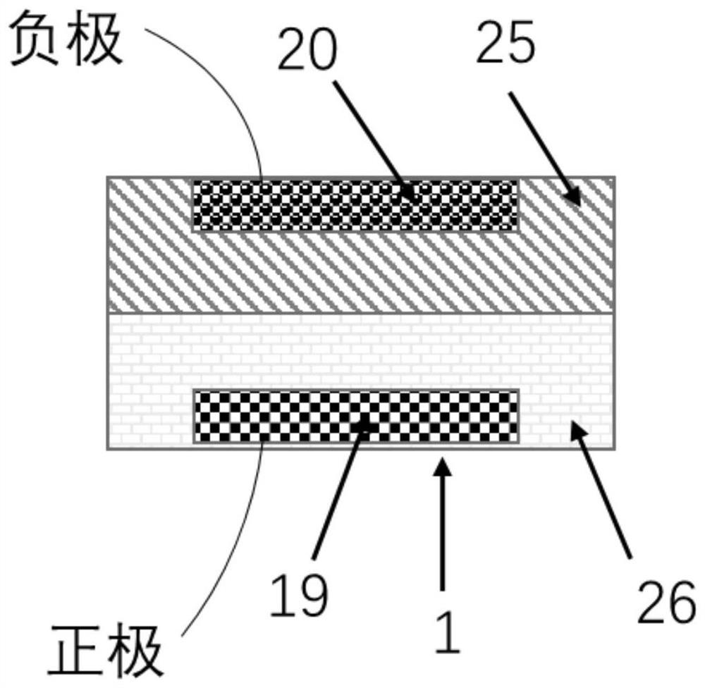
[0022] This embodiment corresponds to a zinc-air self-layering battery, as shown in the attached figure 1 The battery container shown is a sealed polypropylene jar. A disc made of graphite felt is set at the bottom of the battery as the positive current collector of the battery. The surface of the carbon felt is loaded with platinum metal nanoparticles. A zinc plate is set on the upper part of the battery as the negative electrode. There is organic solvent perfluorodecalin in the battery, organic ion compound LiTFSI salt is dissolved, and the aqueous electrolyte is potassium tetrahydroxyzincate (K 2 Zn(OH) 4 ) aqueous solution. Perfluorodecalin is insoluble in water and will sink below the aqueous electrolyte to form a separate phase. When the battery is charged, the positive current collector and the zinc negative electrode are connected to the power supply through an external circuit; when the battery is discharged, the positive current collector and the zinc negative e...
Embodiment 2
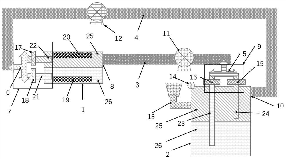
[0025] This embodiment corresponds to a zinc-air self-layering battery system, as shown in the attached figure 1 As shown, the liquid air storage tank is a sealed polypropylene jar, the organic solvent inside is perfluorodecalin, the organic ionic compound LiTFSI salt is dissolved, and the aqueous electrolyte is sodium tetrahydroxyzincate (Na 2 Zn(OH) 4 ) aqueous solution. Perfluorodecalin is insoluble in water and will sink below the aqueous electrolyte to form a separate phase. An air valve is installed on the polypropylene jar, when the air valve is opened, the oxygen in the air will dissolve in perfluorodecalin, and the air valve will be closed after one hour of opening. Through the first liquid pump, perfluorodecalin and aqueous electrolyte flow out of the liquid air storage tank in a ratio of 1:1 (the flow rate is controlled by the first flowmeter and the second flowmeter), and enter the second flowmeter through the first three-way valve. A flow pipe then flows into t...
Embodiment 3
[0027] The difference between this example and Example 2 is that different organic solvents and organic ionic compounds are used, the size of the battery system device is set, and carbon nanotubes are loaded on the positive electrode current collector in the battery as the positive electrode catalyst. This embodiment corresponds to a zinc-air self-layering battery system, as shown in the attached figure 1 As shown, the liquid air storage tank is a sealed polypropylene tank with an inner diameter of 100 cm, a wall thickness of 1 mm, and a height of 100 cm. There are organic solvents 1H, 1H, 5H-octafluoropentyl 1, 1, 2, 2-tetrafluoroethyl ether ( OTE) 200L, dissolved with 1 kg of organic ionic compound tetrabutylammonium bistrifluoromethanesulfonimide, the aqueous electrolyte is 5mol / L tetrahydroxy potassium zincate (K 2 Zn(OH) 4 ) aqueous solution 200L. OTE is insoluble in water and will sink below the aqueous electrolyte to form an independent phase. An air valve is install...
PUM
 Abstract
Description
Claims
Application Information
 - R&D Engineer
- R&D Manager
- IP Professional
- Industry Leading Data Capabilities
- Powerful AI technology
- Patent DNA Extraction
Browse by: Latest US Patents, China's latest patents, Technical Efficacy Thesaurus, Application Domain, Technology Topic.
© 2024 PatSnap. All rights reserved.Legal|Privacy policy|Modern Slavery Act Transparency Statement|Sitemap