Supercharge Your Innovation With Domain-Expert AI Agents!

Heat dissipation device of heating and ventilation compressor frequency converter

A heat dissipation device and compressor technology, applied in the direction of cooling/ventilation/heating transformation, modification of power electronics, chemical instruments and methods, etc., can solve the problem of reducing the heat dissipation effect of heat sinks, increasing the workload of operators, and inconvenient heat sinks Dismantling and replacing problems to achieve the effect of improving heat dissipation, preventing dust from falling randomly, and improving fixing efficiency

Pending Publication Date: 2020-12-01
上海弓通电子科技有限公司
View PDF0 Cites 0 Cited by
  • Summary
  • Abstract
  • Description
  • Claims
  • Application Information

AI Technical Summary

Problems solved by technology

[0003] In order to overcome the deficiencies of the prior art, the object of the present invention is to provide a cooling device for the frequency converter of the HVAC compressor, so as to solve the problem that the dust in the air is easy to adhere to the outer surface of the cooling fins in the above-mentioned background technology, and for a long time After a lot of use and accumulation, it is easy to cover the surface of the heat sink, reducing the heat dissipation effect of the heat sink; and the connection of the heat sink is more cumbersome and flexible, it is not convenient to remove and replace the heat sink in the sleeve, which increases the workload of the operator ; At the same time, there is a lot of dust in the air inside and outside the inverter of the HVAC compressor, which is not convenient for collecting and processing the dust during the heat dissipation process, and it adheres to the surface of the heat dissipation device, which affects the heat dissipation effect.

Method used


Image

  • Heat dissipation device of heating and ventilation compressor frequency converter
  • Heat dissipation device of heating and ventilation compressor frequency converter
  • Heat dissipation device of heating and ventilation compressor frequency converter

Examples


Embodiment

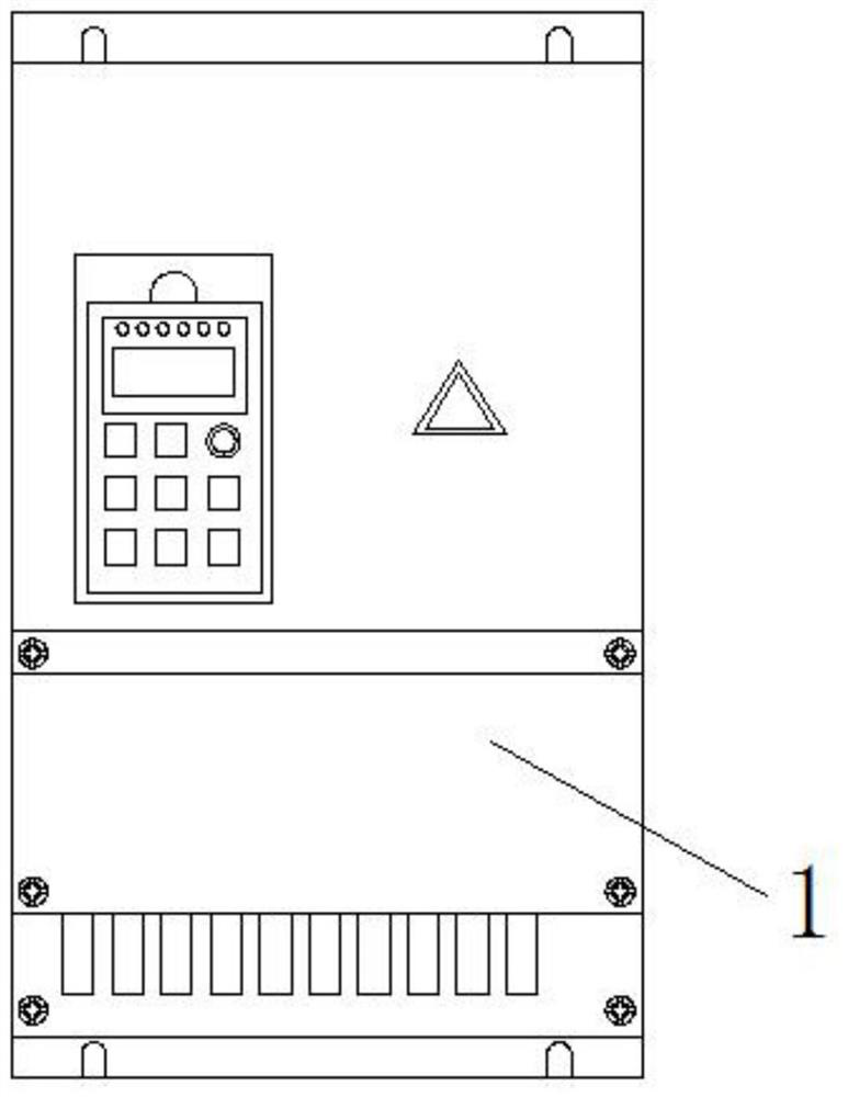
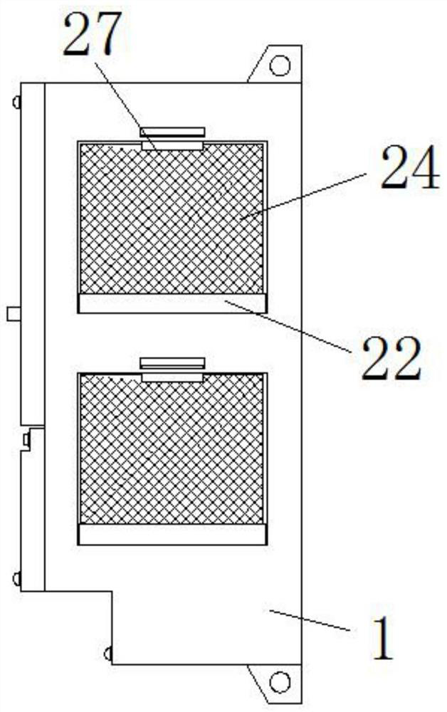
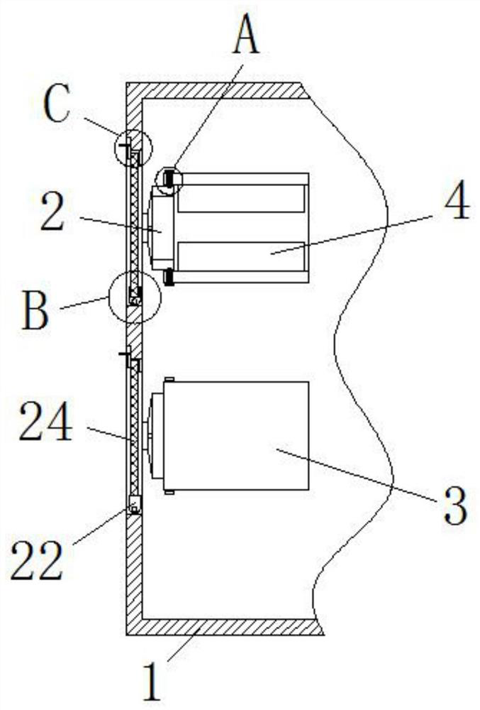
[0030] see Figure 1-6 As shown, the present invention provides a technical solution: a cooling device for a frequency converter of a HVAC compressor, including a housing 1, a cooling fan 2 is fixed on the surface of the inner cavity of the housing 1, and a sleeve is connected to the other end of the cooling fan 2 3. The surface of the inner ring of the sleeve 3 is fixed with a heat sink 4, and one side of the heat sink 4 is provided with a storage tank 5, and the inside of the sleeve 3 is provided with a ring groove 6, and the inside of the ring groove 6 is provided with a ring block 7. The bottom end of the ring block 7 is fixed on the side of the heat sink 4, and the cleaning brush 8 is fixed. The surface of the ring block 7 is fixed on the outside of the sleeve 3. The fixed block 12 is fixed, and the top surface of the ring groove 6 is provided with an arc groove 9. The inner wall surface of the arc groove 9 is engaged with the outer surface of the fixed block 12 to form a...


PUM


Abstract

The invention discloses a heat dissipation device of a heating and ventilation compressor frequency converter. The device comprises a shell, a cooling fan is fixedly arranged on the surface of an inner cavity of the shell, the other end of the cooling fan is connected with a sleeve, cooling fins are annularly and fixedly arranged on the surface of an inner ring of the sleeve, a storage groove is formed in the surface of one side of each cooling fin, and an annular groove is formed in the sleeve. Through shifting a fixing block, the fixing block is driven to move in the arc groove, a cleaning brush can cling to the surface of the cooling fin, the fixing block moves along the sliding groove, the cleaning brush can be driven to slide on the surface of the cooling fin, dust on the outer surfaces of the cooling fins can be cleaned, the problems that in the using process, dust in the air is prone to being attached to the outer surfaces of the cooling fins, the surfaces of the cooling fins are prone to being covered after long-time use and accumulation, and the cooling effect of the cooling fins is reduced accordingly can be avoided, equipment is cleaned and maintained regularly, the contact area between the cooling fins and the air is prone to being increased, and therefore the cooling effect of the whole cooling device is improved are solved.

Description

technical field [0001] The invention belongs to the technical field of heat dissipation, and in particular relates to a heat dissipation device for a frequency converter of a HVAC compressor. Background technique [0002] HVAC compressor frequency converter has heating, ventilation and air conditioning, and can upgrade low-pressure gas to high-pressure gas driven machinery. The frequency converter is the key component of the energy-saving control link. The frequency converter also has many protection functions, such as over-current , overvoltage, overload protection, etc., with the continuous improvement of industrial automation, frequency converters have also been widely used; frequency converters are usually placed in boxes during use to protect components to a certain extent; frequency conversion When the inverter is working, it generates a certain amount of heat, and the cooling device is often used to dissipate heat from the inverter of the HVAC compressor. However, whe...

Claims


Application Information

Patent Timeline
Patent Type & Authority Applications(China)
IPC IPC(8): H05K7/20B08B3/08B08B1/00
CPCH05K7/20909H05K7/209B08B3/08B08B1/30B08B1/12
Inventor 杨雄李静
Owner 上海弓通电子科技有限公司
Features
  • R&D
  • Intellectual Property
  • Life Sciences
  • Materials
  • Tech Scout
  • Unparalleled Data Quality
  • Higher Quality Content
  • 60% Fewer Hallucinations
Learn More