Drainage positioning grouting segment and its construction method

The technology of grouting pipe and grouting pipe is applied in the directions of drainage, earthwork drilling, wellbore/well components, etc. It can solve the problems of many construction links, easy damage to the waterproof layer of the segment, settlement and deformation, etc., and save construction costs. and construction period, broad engineering application prospects, and the effect of ensuring durability

Active Publication Date: 2022-04-22
ZHEJIANG UNIV CITY COLLEGE
View PDF0 Cites 0 Cited by
  • Summary
  • Abstract
  • Description
  • Claims
  • Application Information

AI Technical Summary

Problems solved by technology

However, this method has the following disadvantages: 1. The original waterproof layer of the segment is easily damaged during the drilling process, which threatens the durability of the segment and adversely affects the tunnel and the surrounding environment; 2. There are many construction links on site, It is difficult to deal with emergency segment deformation and prone to hole collapse, resulting in segment damage and economic losses; 3. On-site drilling is easily constrained by the environment. If the external water pressure and soil pressure are too large, it will cause engineering problems such as sudden surge and piping; 4. The crack grouting sealing technology cannot deal with all the segment leakage problems; 5. The effect of groundwater pressure on the segment cannot be reduced or eliminated by the crack grouting sealing method; 6. The grouting reinforcement cannot eradicate the settlement and segment deformation, the drilling holes in the prior art cannot be used multiple times, and the cost is relatively high
[0004] Therefore, in order to repair the problems of settlement deformation and segment leakage during the operation of the tunnel, and in view of the current engineering status of the urban underground environment that is increasingly complex and related grouting reinforcement technology is not perfect, there is an urgent need for a new type of construction that is fast, simple, safe and effective. Grouting reinforcement technology

Method used


Image

  • Drainage positioning grouting segment and its construction method
  • Drainage positioning grouting segment and its construction method
  • Drainage positioning grouting segment and its construction method

Examples


Embodiment Construction

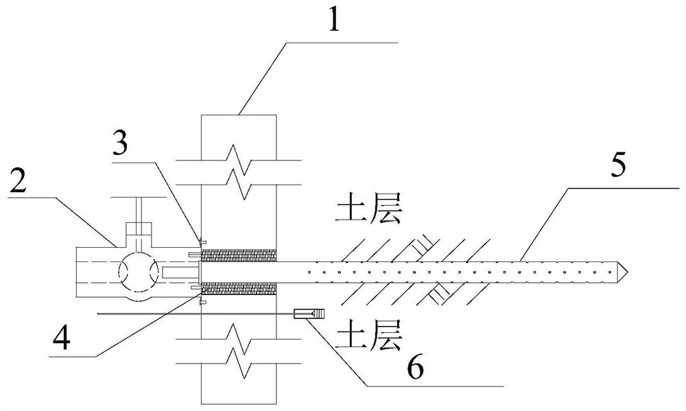
[0052] The present invention will be further described below in conjunction with the accompanying drawings and embodiments.

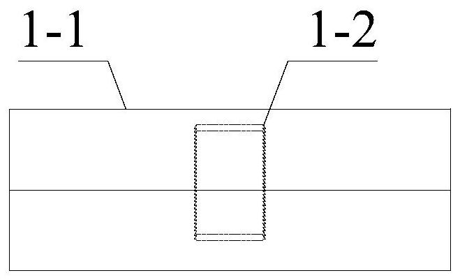
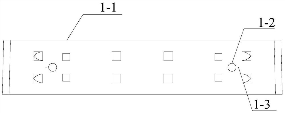
[0053] Such as Figure 1-14 As shown, a drainage positioning grouting segment provided in this embodiment includes a prefabricated segment body 1 and a grouting drainage system; the prefabricated segment body 1 includes a segment solid body 1-1, and the segment solid body 1-1 is provided with a prefabricated borehole 1-2 and a prefabricated water pressure pore sensor installation hole 1-3; the prefabricated borehole 1-2 is prefabricated during the pouring process of the segment, and there is no need to carry out the prefabrication of the segment during the service stage of the tunnel. On-site construction avoids common engineering problems of traditional on-site segment drilling construction technology; the hole wall is threaded for fixing the sealing device, that is, the air bag 4 .

[0054] The grouting drainage system includes a pre-installed valve ...


PUM


Abstract

The invention discloses a drainage positioning grouting segment and a construction method thereof. The drainage positioning grouting segment includes a prefabricated segment main body and a grouting drainage system; Install holes for water pressure pore sensors; the grouting drainage system includes pre-installed valves, pre-embedded air bags, grouting drainage conduits and water pressure pore sensors; when the water pressure collected by the water pressure pore sensors exceeds the force warning value of the segment, Engineering problems such as segment deformation and crack water seepage can be prevented by opening the valve to drain water or first opening the valve to drain water and then grouting reinforcement. The invention adopts prefabricated drilling and pre-embedded grouting drainage system, without on-site drilling and installation of grouting drainage device on the shield segment, and directly drains water through the pre-installed valve and disassembles the valve, and then grouts through the pre-embedded grouting drainage conduit. The prevention and rapid safety treatment of common engineering problems of shield tunnel segments are realized, and the construction cost and construction period are saved.

Description

technical field [0001] The invention relates to the technical field of prefabricated segment production in underground shield subway tunnel engineering, in particular to a drainage positioning grouting segment and a construction method thereof. Background technique [0002] In recent years, the construction of subway tunnels in many cities in my country has entered a stage of great development. Statistics show that as of December 31, 2019, a total of 40 cities in mainland my country have opened urban rail transit operating lines, with an operating mileage of 6,730.27 kilometers, and still maintain a rapid growth trend. In 2019, only 968.77 kilometers of new operating lines in mainland China , including 891.83 kilometers of subway. With the large increase of close construction and the continuous disturbance of vibration to the soil around the tunnel during the operation of the subway, the surrounding environment of the tunnel has changed, resulting in deformation and damage o...

Claims


Application Information

Patent Timeline
Patent Type & Authority Patents(China)
IPC IPC(8): E21D11/00E21D11/08E21D11/10E21D11/38E21B33/126E21F16/02
CPCE21D11/003E21D11/08E21D11/086E21D11/105E21D11/38E21B33/126E21B33/1208E21F16/02
Inventor 章丽莎叶佳欢魏纲李炯韬孙逸夫崔允亮孙苗苗
Owner ZHEJIANG UNIV CITY COLLEGE
Why Eureka
Try Eureka