
Drum brake with cooling function

A drum-type, self-contained technology, applied in the direction of hydraulic drum brakes, brake components, brake actuators, etc., can solve the problems of reducing the service life of drum brakes, reducing braking performance, reducing friction coefficient, etc. The probability of brake failure and the effect of ensuring braking performance

Inactive Publication Date: 2020-12-04
龚植祥
View PDF8 Cites 3 Cited by
  • Summary
  • Abstract
  • Description
  • Claims
  • Application Information

AI Technical Summary

Problems solved by technology

[0003] Since the braking friction of the drum brake occurs on the inner wall of the drum brake, the heat generated during the braking process cannot be dissipated in time. Therefore, when braking continuously on a long downhill, the braking performance will have obvious thermal decline. The heat expansion caused will increase the diameter of the brake drum and reduce the sensitivity of braking. In order to reduce the influence of heat, it is often seen in daily life that truck wheels are equipped with water tanks to water the tires during continuous braking. The purpose of the water is to reduce the temperature of the drum brake, but the water will enter the drum brake from the gap to reduce the friction coefficient and reduce the braking performance. On the other hand, this kind of water is usually untreated, and there will be impurities in it Corrosion may develop, reducing drum brake life
[0004] When the goods are loaded, the quality of the goods on both sides cannot be guaranteed to be the same. In particular, due to habits or the direction of loading, it may frequently occur that the quality of one side is heavier than the other. When braking, the heavier side needs to be Provide higher braking force, that is, the heavier side has greater friction and wears faster. When there is a significant difference in the matching clearance between the two sides, the difference in braking force on both sides will cause the truck to lose balance. more prone to rollover

Method used


Image

  • Drum brake with cooling function
  • Drum brake with cooling function
  • Drum brake with cooling function

Examples


Embodiment Construction

[0020] The following will clearly and completely describe the technical solutions in the embodiments of the present invention with reference to the accompanying drawings in the embodiments of the present invention. Obviously, the described embodiments are only some, not all, embodiments of the present invention. Based on the embodiments of the present invention, all other embodiments obtained by persons of ordinary skill in the art without making creative efforts belong to the protection scope of the present invention.

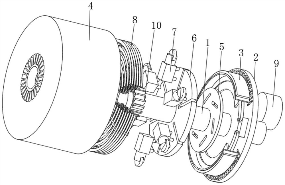
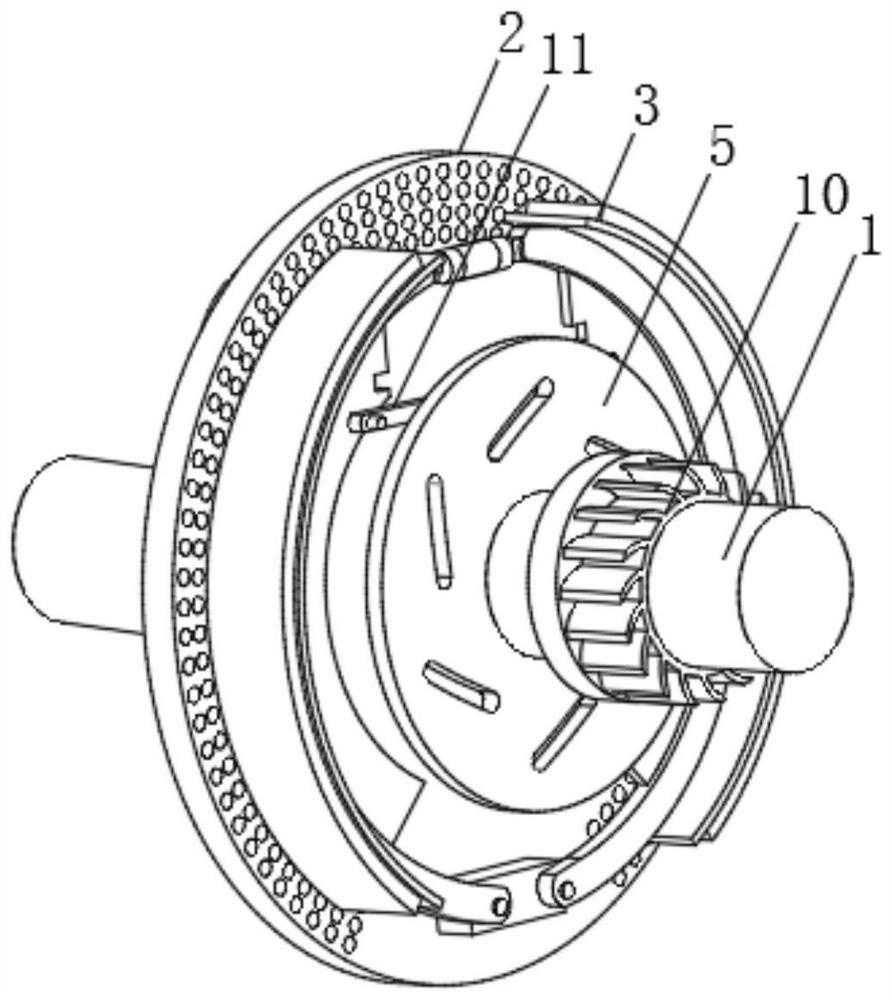
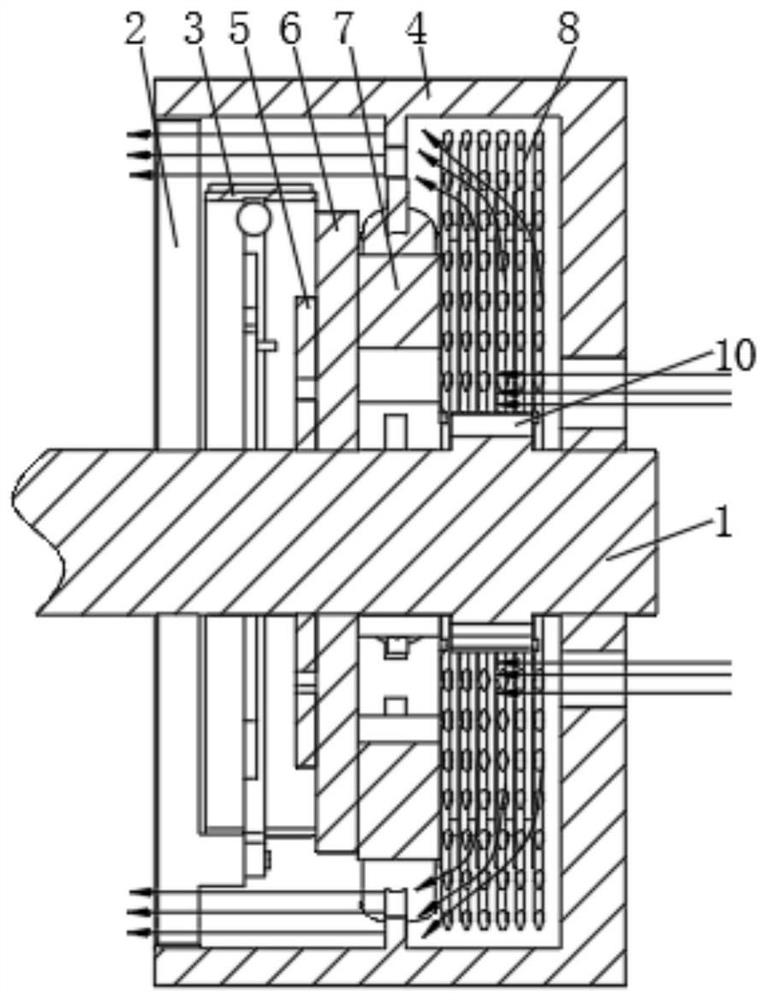
[0021] see figure 1 , a drum brake with self-cooling, including an axle 1 and a mounting seat 2, the mounting seat 2 is fixedly installed on the chassis of the truck, the axle 1 passes through the mounting seat 2 and is fixedly connected to a brake drum 4, and the brake drum 4 is connected with the As the axle 1 rotates and rotates, the brake drum 4 is sleeved on the outside of the mounting base 2, the end face of the mounting base 2 is hinged with a brake sho...


PUM


Abstract

The invention relates to the technical field of brake equipment, and discloses a drum brake with a cooling function. The drum brake comprises an axle and a mounting base, wherein the axle penetrates through the mounting base to be fixedly connected with a brake drum, and a brake shoe is hinged to the end face of the mounting base. According to the drum brake with the cooling function, during continuous braking during long downhill, rotation of an adjusting disc drives a compression cylinder to do piston motion, compressed gas enters an external condenser, heat in the brake drum is conveyed tothe external condenser, and the interior of the brake drum is kept in a low-temperature state through the external condenser; and secondly, certain braking capacity is improved under the action of thebrake drum and the compression cylinder, a considerable part of braking force is provided by the compression cylinder when the driving speed of the automobile is adjusted by slightly stepping on thebrake, and the frequency of slightly stepping on the brake is far higher than that of heavily stepping on the emergency brake in daily use, so that the abrasion speed of the brake shoe during daily driving is reduced.

Description

technical field [0001] The invention relates to the technical field of brake equipment, in particular to a drum brake with self-cooling. Background technique [0002] Drum brakes consist of a brake drum and a brake shoe. When braking, the hydraulic cylinder drives the brake shoe to open and rubs against the inner surface of the brake drum that rotates with the wheel, forcing the brake drum and the wheel to slow down. When moving, under the action of friction, the pressure between the brake shoe and the brake drum increases, which plays a good self-braking effect. Therefore, generally large-scale trucks use more drum brakes. [0003] Since the braking friction of the drum brake occurs on the inner wall of the drum brake, the heat generated during the braking process cannot be dissipated in time. Therefore, when braking continuously on a long downhill, the braking performance will have obvious thermal decline. The heat expansion caused will increase the diameter of the brake ...

Claims


Application Information

Patent Timeline
IPC IPC(8): F16D51/24F16D65/833F16D65/14F16D121/04
CPCF16D51/24F16D65/14F16D65/833F16D2121/04
Inventor 龚植祥
Owner 龚植祥
Learn More