Microfluid dielectrophoresis separation device and manufacturing method of microfluid dielectrophoresis separation device

A separation device, dielectrophoresis technology, which is applied in measurement devices, individual particle analysis, material analysis by electromagnetic means, etc. The effect of matching difficulty

Active Publication Date: 2020-12-04
SOUTH CHINA NORMAL UNIVERSITY
View PDF5 Cites 3 Cited by
  • Summary
  • Abstract
  • Description
  • Claims
  • Application Information

AI Technical Summary

Problems solved by technology

Although this electrode can achieve effective separation of particles, it requires pre-aggregation operation, which is cumbersome and expensive

Method used


Image

  • Microfluid dielectrophoresis separation device and manufacturing method of microfluid dielectrophoresis separation device
  • Microfluid dielectrophoresis separation device and manufacturing method of microfluid dielectrophoresis separation device
  • Microfluid dielectrophoresis separation device and manufacturing method of microfluid dielectrophoresis separation device

Examples


Embodiment 1

[0079] Figure 5 A schematic diagram of the separation of yeast cells and PS particles using the microfluidic dielectrophoresis separation device of the embodiment of the present invention is shown. In this embodiment, red polystyrene microspheres (PS particles) with a particle size of 7 microns are used to mix with yeast cells , to test the separation effect of the microfluidic dielectrophoretic separation device.

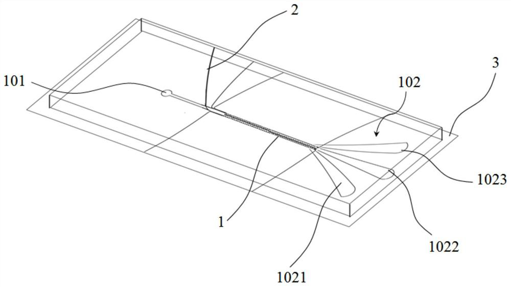
[0080] Firstly, the particle mixture is passed into the microfluidic channel 1 from the inlet 101 . Therefore, the mixed particles do not need to undergo pre-agglomeration operations. The conductivity of the particle mixture is preferably in the range of 10-100ms / cm. When separating yeast and PS particles, a 20Vpp, 500kHz sinusoidal signal is used to generate an electric field. like Figure 5 As shown, yeast cells are subjected to a positive dielectrophoretic force (pDEP) and move towards the high-field region at the tip of the electrode. The curved structure ...

Embodiment 2

[0083] Figure 6(a) and Figure 6(b) show a schematic diagram of the separation of red blood cells and tumor cells using the microfluidic dielectrophoretic separation device of the embodiment of the present invention, and the left figure of Figure 6(a) shows red blood cells It is a schematic diagram of the state of the tumor cells just entering the microfluidic channel 1 , and the right figure of FIG. In the second embodiment, the same parameters of the microfluidic dielectrophoretic separation device as in the first embodiment are used to verify the feasibility of the microfluidic dielectrophoretic separation device for separating biological cells.

[0084] The tumor cells may be breast cancer cells (MDA-MB-231), and 17Vpp, 75kHz sinusoidal signals are used to generate an electric field for separating erythrocytes and breast cancer cells. The mixed liquid of red blood cells and breast cancer cells is passed into the microfluidic channel 1 from the inlet 101, and after being pow...


PUM

PropertyMeasurementUnit
heightaaaaaaaaaa
lengthaaaaaaaaaa

Abstract

The invention relates to a microfluid dielectrophoresis separation device and a manufacturing method of the microfluid dielectrophoresis separation device. The microfluid dielectrophoresis separationdevice comprises: a microfluid channel; and an electrode arranged corresponding to the microfluid channel, wherein the electrode comprises a first electrode area and a second electrode area which aresequentially arranged in the flowing direction of fluid, the first electrode area is close to the inlet of the microfluid channel, the sides, facing the interior of the microfluid channel, of first grounding electrodes located on the two sides of the first electrode area are an arc-shaped electrode array, and a second central electrode located in the middle of the second electrode area is a lemon-shaped electrode array. The structures of the electrode and the microfluid channel are designed, pre-aggregation operation is not needed, and efficient separation of particles can be achieved throughthe mutual assistance effect of the electrode and the microfluid channel; and meanwhile, the integration performance of the device can be remarkably improved, the difficulty of mutual integration or matching with external equipment is reduced, and the applicability of the device is improved.

Description

technical field [0001] The invention relates to the technical field of particle separation, in particular to a microfluid dielectrophoretic separation device and a manufacturing method of the microfluid dielectrophoretic separation device. Background technique [0002] Dielectrophoresis (DEP) separation technology has been widely used in particle sorting, biological cell sorting and other fields. Separation technologies based on microfluidic platforms allow the size reduction of separated samples while minimizing sample consumption and offer the possibility of active real-time control of the separation process. Therefore, the separation technology based on microfluidics has developed rapidly in recent years and is widely used in biological and medical fields. In order to achieve a good separation effect, the separation technology based on the microfluidic platform and the dielectrophoresis separation technology are combined in the prior art. The realization of dielectropho...

Claims


Application Information

Patent Timeline
Patent Type & Authority Applications(China)
IPC IPC(8): G01N27/447G01N15/10
CPCG01N27/4473G01N27/44791G01N15/1056G01N15/1031G01N2015/1006G01N2015/1081
Inventor 水玲玲申诗涛金名亮
Owner SOUTH CHINA NORMAL UNIVERSITY
Why Eureka
Try Eureka