Method for controlling temperature of reduction rotary kiln by optimizing and adjusting fuel amount and air volume

An air volume control and rotary kiln technology, applied in the field of rotary kiln, can solve the problems of volatile matter and CO escape, the inability to accurately monitor the temperature online and real-time, and the uncoordinated fuel system.

Active Publication Date: 2020-12-08
ZHONGYE-CHANGTIAN INT ENG CO LTD
View PDF5 Cites 5 Cited by
  • Summary
  • Abstract
  • Description
  • Claims
  • Application Information

AI Technical Summary

Problems solved by technology

[0012] In view of the existing technology, the temperature in the rotary kiln along the kiln length is uneven, easy to form rings, and the reduction efficiency is low; the high temperature section is short, volatile matter and CO escape into the reburning chamber, and the temperature is difficult to control, the output is small, and the energy consumption is low. High; the temperature cannot be accurately monitored in real time on-line, causing techni...

Method used


Image

  • Method for controlling temperature of reduction rotary kiln by optimizing and adjusting fuel amount and air volume
  • Method for controlling temperature of reduction rotary kiln by optimizing and adjusting fuel amount and air volume
  • Method for controlling temperature of reduction rotary kiln by optimizing and adjusting fuel amount and air volume

Examples


Embodiment 1

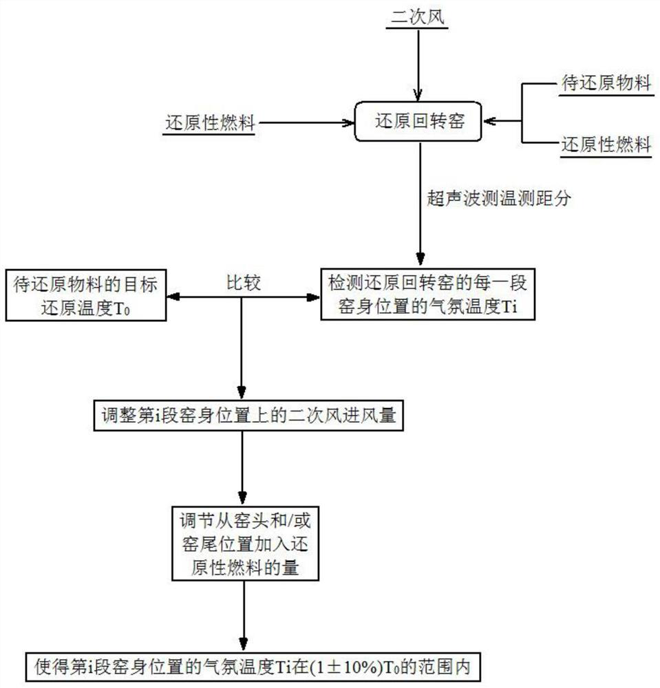
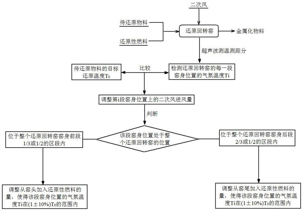
[0178] A method for controlling the temperature of the reduction rotary kiln by optimizing and adjusting the fuel volume and air volume. The reduction rotary kiln 1 is provided with an ultrasonic temperature measurement and distance measuring analyzer 2, and the kiln body of the reduction rotary kiln 1 is divided into n sections, and each section of the kiln body is provided with an ultrasonic temperature measuring and ranging analyzer 2. Secondary air nozzles 3, and each secondary air nozzle 3 is connected to a fan 4. The method includes the following steps:

[0179] 1) Load the material to be reduced into the reduction rotary kiln 1, add reducing fuel at the kiln head 101 and the kiln tail 102 of the reduction rotary kiln 1, and inject secondary air from the secondary air nozzle 3 on each section of the kiln.

[0180] 2) A burner 103 is provided at the position of the kiln head 101 of the reduction rotary kiln 1, and the material to be reduced is burned and reduced by the re...

Embodiment 2

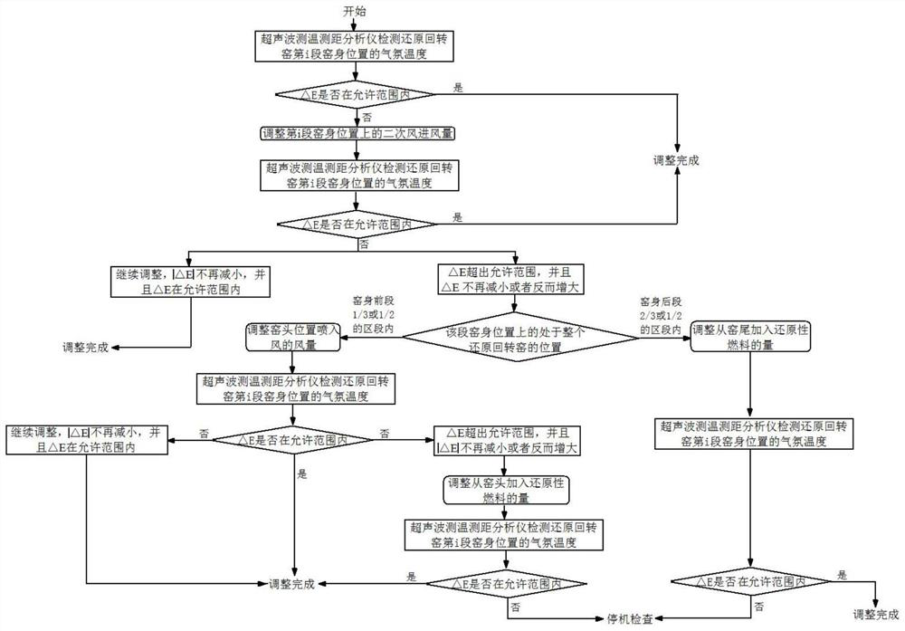
[0190] Repeat Example 1, but compare the target reduction temperature T 0 And the atmospheric temperature Ti at the position of the kiln body of the i-th section is specifically: Calculate the difference between the atmospheric temperature of the kiln body position of the i-th section and the target reduction temperature △E:

[0191] ΔE=T i -T 0 .

Embodiment 3

[0193] Repeat Example 2, except that step 5) is specifically:

[0194] 5a) Adjust the fan 4 connected to the secondary air nozzle 3 on the kiln body position of the i-th section, so as to adjust the secondary air intake air volume on the kiln body position of the i-th section.

[0195] 5b) The ultrasonic temperature measurement and distance analyzer 2 detects the atmospheric temperature Ti at the position of the kiln body in this section of the reduction rotary kiln 1 again, and compares the target reduction temperature T 0 The difference ΔE is obtained from the adjusted atmospheric temperature Ti at the kiln body position of the i-th section.

[0196] To analyze and compare:

[0197] 5b1) If the difference △E between the atmospheric temperature at the position of the kiln body and the target reduction temperature is within the range of ±10°C after adjusting the secondary air intake air volume at the position of the kiln body, the current secondary air intake is maintained in...


PUM


Abstract

The invention discloses a method for controlling the temperature of a reduction rotary kiln by optimizing and adjusting the fuel amount and the air volume. An ultrasonic temperature and distance measurement analyzer is additionally arranged on a kiln head cover of a rotary kiln in order to monitor the temperature in the kiln length direction online in real time. a series of secondary air nozzles are installed on a kiln body in the kiln length direction, and the air volume of the secondary air nozzle at a corresponding point is changed according to the difference between the temperature of a measured point and a target temperature, or the amount of reductive fuel added from the kiln head and/or the kiln tail of the reduction rotary kiln is adjusted. The uniformity of a temperature field inthe kiln in the kiln length direction is ensured. The local temperature is prevented from being too high or too low, ring formation in the rotary kiln is avoided, a longer high-temperature zone is provided for reduced materials, and the product quality index is remarkably improved.

Description

technical field [0001] The invention relates to a method for controlling the temperature of a reduction rotary kiln, in particular to a method for controlling the temperature of the reduction rotary kiln by optimally adjusting the fuel volume and air volume, and belongs to the technical field of rotary kilns. Background technique [0002] Environmental protection departments have long been concerned about SO 2 and NOx emission charges, as carbon emission reduction pressure intensifies, China's carbon emission trading system is about to operate, CO 2 Emissions will also be gradually included in the payment scope. The traditional long process will bring a higher cost burden to steel companies than the short process; the development trend of the world's steel industry is gradually transitioning from the long process of "blast furnace-converter" to the short process of "direct reduction (scrap)-electric furnace". will increase from 66.8% to 70%, and many blast furnaces will be...

Claims


Application Information

Patent Timeline
IPC IPC(8): F27B7/42F27B7/34F27B7/36F27D19/00C21B13/08
CPCF27B7/42F27B7/36F27B7/34F27D19/00C21B13/08F27D2019/0003F27D2019/004F27D2019/0043F27D2019/0046
Inventor 胡兵曾小信
Owner ZHONGYE-CHANGTIAN INT ENG CO LTD
Why Eureka
Try Eureka