
A delay circuit and electronic system including same

A delay circuit and current technology, applied in electronic switches, pulse manipulation delays, control/regulation systems, etc., can solve the problems of high power consumption, slowness, and inaccurate operation of electronic devices, and achieve low power consumption, high precision, and optimization. efficacy effect

Active Publication Date: 2020-12-08
ARTERY TECH CO LTD
View PDF8 Cites 2 Cited by
  • Summary
  • Abstract
  • Description
  • Claims
  • Application Information

AI Technical Summary

Problems solved by technology

Traditional delay circuits have many disadvantages
For example, a slow input slew of an output stage in a conventional delay circuit can result in a large power dissipation of this output stage
As another example, the circuit characteristics of traditional delay circuits are quite sensitive to process, voltage and temperature (which may be referred to as PVT for short), especially, there is a large delay variation (delay variation) on PVT, which may cause electronic devices inaccurate operation

Method used


Image

  • A delay circuit and electronic system including same
  • A delay circuit and electronic system including same
  • A delay circuit and electronic system including same

Examples


Embodiment Construction

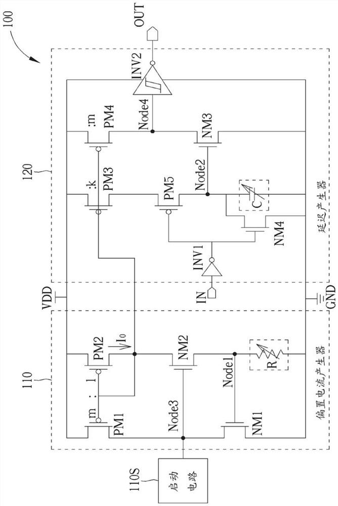
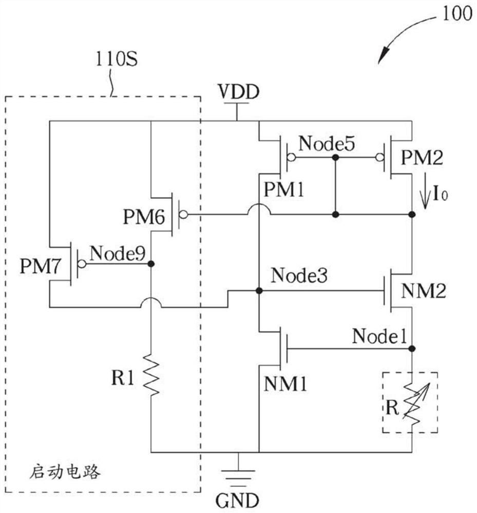
[0046] figure 1 It is a schematic diagram of a delay circuit 100 according to an embodiment of the present invention. The delay circuit 100 may include an input terminal IN, an output terminal OUT, a bias current generator 110, a startup circuit 110S, and a delay generator 120, wherein the input terminal IN may be used to input an input signal to the delay circuit 100, And the output terminal OUT can be used to output a delayed signal from the delay circuit 100 . The delay circuit 100 can operate according to a first reference voltage and a second reference voltage, and can include transistors with different types of channels, such as transistors belonging to the first type and the second type, respectively. figure 1 Some types of Metal Oxide Semiconductor Field Effect Transistors (Metal Oxide Semiconductor Field Effect Transistor, which may be referred to simply as "MOSFET") are used in the architecture shown, such as P-type and N-type MOSFET, but the invention is not limit...


PUM


Abstract

The invention discloses a delay circuit and an electronic system having the same. The delay circuit may include an input terminal, an output terminal, a bias current generator, and a delay generator.The bias current generator is coupled between the first reference voltage and the second reference voltage and is used for generating a bias current. The delay generator is coupled between the first reference voltage and the second reference voltage and is used for generating delay of the delay signal relative to the input signal according to the bias current. The bias current generator comprisesa current mirror, a current module and a transistor. The delay generator includes a first current mirror circuit, a second current mirror circuit, a transistor, a capacitor, a switching circuit, and aSchmidt inverter, wherein an output terminal is coupled to the Schmidt inverter to output a delay signal. Compared with a traditional delay circuit, the delay circuit provided by the invention has lower power consumption and higher precision in process, voltage and temperature.

Description

technical field [0001] The present invention relates to electronic circuits, in particular to a delay circuit and an electronic system equipped with the delay circuit. Background technique [0002] Delay circuits are important basic circuits in electronic devices. Traditional delay circuits have many disadvantages. For example, a slow input slew at an output stage in a conventional delay circuit can result in significant power dissipation in that output stage. As another example, the circuit characteristics of traditional delay circuits are quite sensitive to process, voltage and temperature (which may be referred to as PVT for short), especially, there is a large delay variation (delay variation) on PVT, which may cause electronic devices inaccurate operation. Therefore, a novel architecture is needed to improve the overall performance of the electronic system. Contents of the invention [0003] An object of the present invention is to disclose a delay circuit and an ...

Claims


Application Information

Patent Timeline
Patent Type & Authority Applications(China)
IPC IPC(8): H03K5/134H03K17/28
CPCH03K5/134H03K17/28G05F1/468H03K2005/00202G05F3/262
Inventor 王正香张文龙王海涛
Owner ARTERY TECH CO LTD
Learn More