Multifunctional treatment catheter

A multi-functional, catheter technology, applied in the field of medical devices, can solve the problems of small thrombus falling off, long suction time, unfavorable patient recovery, etc., to reduce the probability of thrombus escape, reduce costs and medical insurance costs, and improve vascular patency rate. Effect

Active Publication Date: 2020-12-11
玮铭医疗器械(上海)有限公司
View PDF10 Cites 2 Cited by
  • Summary
  • Abstract
  • Description
  • Claims
  • Application Information

AI Technical Summary

Problems solved by technology

[0004] Existing thrombectomy stents are generally laser-engraved, and the surface is made of different grids. The thrombus is embedded in the mesh of the stent, and its clamping force is relatively limited. During the thrombectomy process, the thrombus is easy to fall off or break from the thrombus retrieval stent. A small thrombus is formed and falls off. Under the action of blood flow, it escapes to a small blood vessel farther away, and will not be able to recapture the thrombus, resulting in the risk of secondary stroke. Negative pressure in the lumen, because the diameter of the tube body is limited by the diameter of the blood vessel, the nozzle is generally small, the suction force is not enough, and the suction time is long, causing a lot of pain to the patient; the existing thrombectomy cannot be performed simultaneously with the stent (mechanical) Plugs and Catheter Suction Plugs
In addition, it has been found from relevant literature that after using catheter suction, stent retrieval is needed again for up to 65% of the cases. Once rescue is used, a microcatheter must be added to deliver the thrombectomy stent, which is troublesome for doctors to operate. The operation time is long, which is not conducive to the recovery of the patient, and the cost borne by the patient is also high

Method used


Image

  • Multifunctional treatment catheter
  • Multifunctional treatment catheter
  • Multifunctional treatment catheter

Examples


Embodiment 1

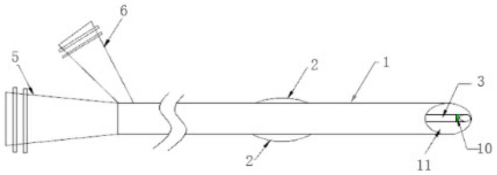
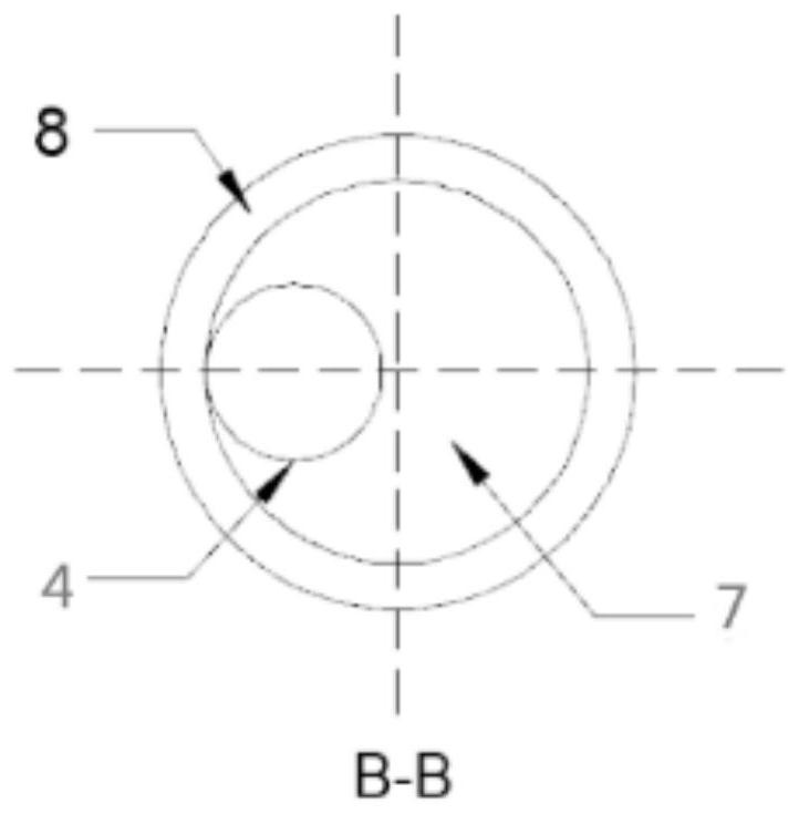
[0040] Such as figure 1 , image 3 As shown, Embodiment 1 of the present invention provides a multifunctional therapeutic catheter, a catheter body 1 and a balloon 2 coated on the outer wall of the catheter body 1, a microcatheter 3 is arranged in the catheter body 1, and the microcatheter 3 The interior is hollow to form a microcatheter lumen 4, a suction inlet 5 is provided at the proximal end of the catheter body 1, and a pressure inlet 6 is also provided on one side of the proximal end of the catheter body 1; wherein, the Catheter body 1 is a three-lumen catheter that does not communicate with each other, including a suction lumen 7, a pressure lumen 8, and a microcatheter inner lumen 4. The suction lumen 7 communicates with the suction inlet 5, and the pressure lumen The cavity 8 communicates with the pressure inlet 6 .

[0041] The suction lumen 7 and the inflation lumen 8 are arranged coaxially along the central axis where the center of the catheter body 1 is located,...

Embodiment 2

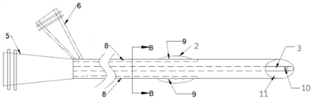
[0044] Such as Figure 1~3 As shown, Embodiment 2 of the present invention provides a multifunctional therapeutic catheter, a catheter body 1 and a balloon 2 coated on the outer wall of the catheter body 1, a microcatheter 3 is arranged in the catheter body 1, and the microcatheter 3 The interior is hollow to form a microcatheter lumen 4, a suction inlet 5 is provided at the proximal end of the catheter body 1, and a pressure inlet 6 is also provided on one side of the proximal end of the catheter body 1; wherein, the Catheter body 1 is a three-lumen catheter that does not communicate with each other, including a suction lumen 7, a pressure lumen 8, and a microcatheter inner lumen 4. The suction lumen 7 communicates with the suction inlet 5, and the pressure lumen The cavity 8 communicates with the pressure inlet 6 .

[0045] The suction lumen 7 and the inflation lumen 8 are arranged coaxially along the central axis where the center of the catheter body 1 is located, the micr...

Embodiment 3

[0049] Such as Figure 4~5 As shown, Embodiment 3 of the present invention provides a multifunctional therapeutic catheter kit, including the multifunctional therapeutic catheter shown in Embodiment 2, and a syringe 12 and a connecting valve 13 used in conjunction with the multifunctional therapeutic catheter. The internal thrombus removal bracket 14; the syringe 12 is detachably arranged on the pressure inlet 6 to pressurize the balloon 2 so that the proximal blood flow can be blocked to prevent small blood flow during the suction process. The tether escapes to the small blood vessel at the far end; the connecting valve is a Y valve, and one end of the Y valve is connected to a suction pump. When the suction pump is turned on, the main body of the catheter sucks the inner cavity to generate negative pressure, and suction starts at 11 oblique incisions. Thrombosis.

[0050] Such as Figure 4 Shown is a schematic diagram of the catheter set during the suction plug procedure. ...


PUM


Abstract

The invention relates to the field of medical instruments, in particular to a multifunctional treatment catheter. The multifunctional treatment catheter comprises a catheter body and a balloon wrapping the outer wall of the catheter body, wherein a micro-catheter is arranged in the catheter body, the inner part of the micro-catheter is hollow to form a micro-catheter inner cavity channel, a suction inlet is formed in the near end of the catheter body, and a pressurizing inlet is further formed in one side of the near end of the catheter body; the catheter body is a three-cavity catheter whichis not in communication with the catheter body, the three-cavity catheter comprises a suction cavity channel, a pressurizing cavity channel and a micro-catheter inner cavity channel, the suction cavity channel communicates with the suction inlet, the pressurizing cavity channel communicates with the pressurizing inlet, and the catheter not only can block blood flow, but also has a thrombus suctionfunction. The micro-catheter is arranged in the multifunctional treatment catheter, and a thrombectomy stent can be conveyed for mechanical thrombectomy. When catheter thrombus suction is performed,stent thrombus taking can be performed at the same time, so that the operation time is shortened, and expenses borne by a patient and medical insurance expenses are reduced.

Description

technical field [0001] The invention belongs to the field of medical equipment, and more specifically, the invention relates to a multifunctional treatment catheter. Background technique [0002] Cardiovascular and cerebrovascular embolism may cause myocardial infarction, stroke and other diseases, which pose a huge threat to human life and health. The current main treatment methods include stent (mechanical) thrombectomy and catheter aspiration. Mechanical thrombectomy and catheter aspiration are both to remove thrombus from human blood vessels through physical methods, so as to recanalize the blood vessels and restore the normal flow of blood, so as to achieve the purpose of treatment. [0003] The main principle of mechanical thrombectomy is to send a thrombus retrieval stent made of memory alloy material to the lesion with the aid of a guide wire and a catheter. After the thrombus retrieval stent is released, it captures and pulls the thrombus into the catheter and takes...

Claims


Application Information

Patent Timeline
Patent Type & Authority Applications(China)
IPC IPC(8): A61B17/22
CPCA61B17/22A61B2017/22062A61B2017/22067A61B2017/22079
Inventor 吴健平赵杰曹维拯何家乐李志刚王国辉
Owner 玮铭医疗器械(上海)有限公司
Why Eureka
Try Eureka