Blisk electrolytic machining device and method for blade full-profile liquid supply

A technology of integral blisk and processing device, which is applied in electrochemical machining equipment, metal processing equipment, supply of processing working medium, etc. Blisk and other problems, to achieve the effect of increasing the stability of the flow field, increasing the pressure and flow rate, and stabilizing the processing

Active Publication Date: 2020-12-11
NANJING UNIV OF AERONAUTICS & ASTRONAUTICS
View PDF4 Cites 11 Cited by
  • Summary
  • Abstract
  • Description
  • Claims
  • Application Information

AI Technical Summary

Problems solved by technology

In the current method of electrolytic processing of the whole blisk, GE and Ex-O-Cell of the United States use the side flow method to process the blisk. Integral block electrodes, so integral blisks with narrow cascade passages cannot be machined
Nanjing University of Aeronautics and Astronautics proposed a method of electrolytic machining of the overall blisk profile with a three-dimensional composite flow field (see the patent "Electrolytic machining device and method for an integral blisk profile based on a three-dimensional composite flow field", application number 201300453340.8 Applicant Nanjing Aerospace Inventor Liu Jiawan Longkai (Xu Zhengyang) and Zhu Dong), the flow field mode is combined with liquid supply from the intake side to the exhaust side and from the root to the tip of the blade, effectively solving the problem of uneven electrolyte distribution in the side flow flow field , but it is prone to lack of liquid at the exhaust side
Nanjing University of Aeronautics and Astronautics proposed a jig and method for electrolytic machining with independent liquid supply for blade partitions and air-tight layers (see patent "Electrolytic machining jig and method for blade partitions with independent liquid supply and air-tight layers", application number 201710201908.2 Applicant The inventor of Nanjing University of Aeronautics and Astronautics Zhu Dong Zhao Jibin Xu Zhengyang Liu Jia) This flow field method effectively improves the flow field stability of the processing blade at the intake and exhaust edges, and the upper and lower electrolyte flows along the tangential direction of the intake and exhaust edges. This technology is only suitable for blade processing, and cannot realize the processing of the whole blisk

Method used


Image

  • Blisk electrolytic machining device and method for blade full-profile liquid supply
  • Blisk electrolytic machining device and method for blade full-profile liquid supply
  • Blisk electrolytic machining device and method for blade full-profile liquid supply

Examples


Embodiment Construction

[0030] Below in conjunction with accompanying drawing, concrete implementation process of the present invention is described in detail as follows:

[0031] The process of electrolytically machining workpieces by using the "Integral Blisk Electrolytic Machining Device and Method for Supplying Liquid to the Whole Contour of the Blade" of the present invention includes the following steps:

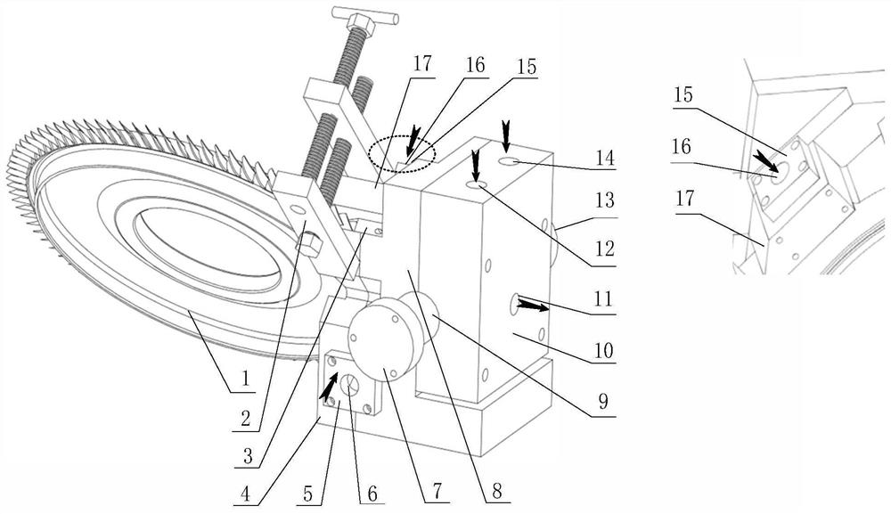
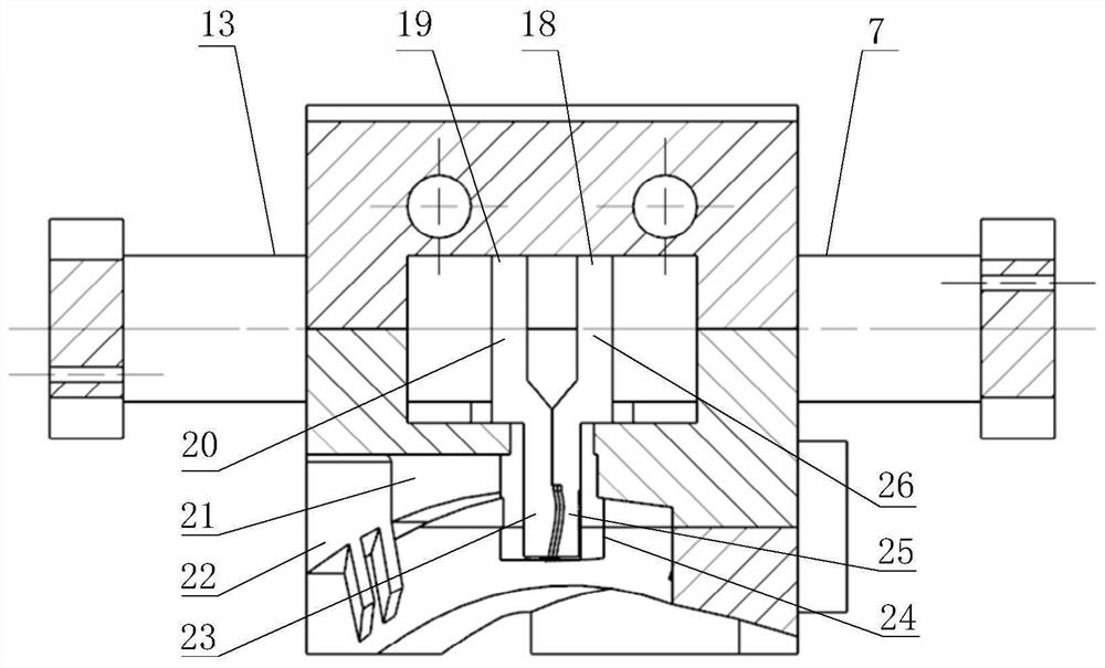
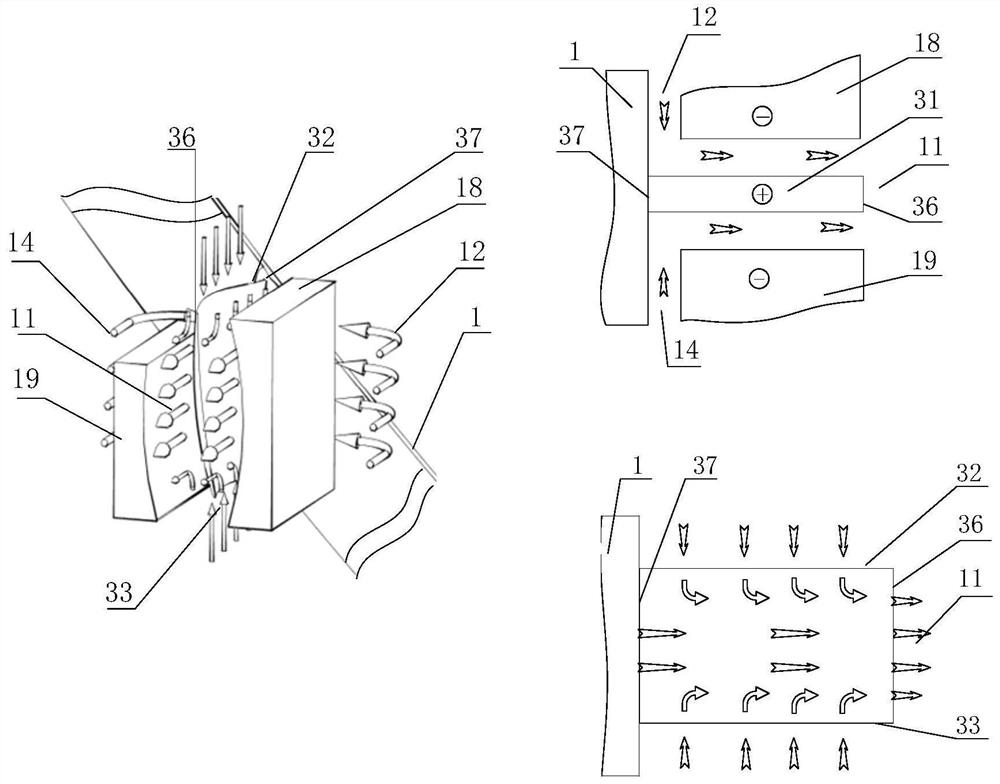
[0032] Step 1, install the cathode and the cathode rod. The leaf back cathode 18 is connected to the leaf back cathode rod 7, and the leaf basin cathode 19 is connected to the leaf basin cathode rod 13, and the leaf back cathode rod 3 and the leaf basin cathode rod 13 are respectively installed on the numerically controlled motion shafts that move linearly toward each other. The cathode rod is connected to the negative pole of the power supply.

[0033] Step 2, install the blisk workpiece 1 as a whole. The electrolytic machining fixture is installed on the fixed base, the whole blisk workpi...


PUM


Abstract

The invention relates to a blisk electrolytic machining device and a method for blade full-profile liquid supply, and belong to the field of electrolytic machining. The blisk electrolytic machining device are used for correspondingly supplying electrolyte to a blade basin, a blade back, an air inlet edge and an air outlet edge of a blade. The clamp body is provided with a main liquid supply flow channel and an auxiliary liquid supply flow channel; the main liquid supply flow channel comprises a blade back flow channel and a blade basin flow channel which are used for supplying the electrolyteto the blade back and the blade basin machining area correspondingly, and liquid inlets of the main liquid supply flow channel are formed in the back surface of a blade back cathode and the back surface of a blade basin cathode; the auxiliary liquid supply flow channel comprises an air inlet side flow channel and an air outlet side flow channel which are used for supplying the electrolyte to the blade air inlet side machining area and the blade air outlet side machining area correspondingly, and liquid inlets of the auxiliary liquid supply flow channel are formed above the blade blank air inlet side and below the blade blank air outlet side; and the blade back cathode, the blade basin cathode, the blisk workpiece and the clamp body form a closed flow field mode in which the electrolyte ineach flow channel is independently controlled. The method is characterized in that liquid is supplied to the whole profile of the blade, the uniformity of a flow field of a machining area is improved,the machining stability and repeated precision of air inlet and outlet edges are improved, and the whole-profile molded surface of the blisk is machined.

Description

technical field [0001] The invention relates to an electrolytic machining device and method for an integral blisk for liquid supply to the full contour of the blade, and belongs to the technical field of electrolytic machining. Background technique [0002] Electrolytic machining is a process that uses the principle of anodic dissolution of metal in the electrolyte, and processes the workpiece according to a certain shape and size with the help of a pre-formed cathode. Electrolytic machining has many advantages such as high processing efficiency, no loss of tools, good surface quality, and wide processing range. It has been applied in aviation, aerospace, weapons and other industries. [0003] The flow field is an important factor affecting the stability, surface quality and machining repeatability of electrolytic machining. A reasonable flow field design is the basis for the smooth progress of electrolytic machining. In the current method of electrolytic processing of the ...

Claims


Application Information

Patent Timeline
Patent Type & Authority Applications(China)
IPC IPC(8): B23H3/00B23H3/10
CPCB23H3/00B23H3/10
Inventor 朱栋郭建伟朱荻
Owner NANJING UNIV OF AERONAUTICS & ASTRONAUTICS
Why Eureka
Try Eureka