Air compressor crank double-end synchronous positioning and clamping device

A technology of synchronous positioning and clamping devices, which is applied in the direction of positioning devices, clamping, metal processing machinery parts, etc., can solve the problems of difficult synchronization of position adjustment, low precision of parts processing, and inability to meet processing requirements, etc., to increase the adjustment stroke Effect

Pending Publication Date: 2020-12-11
昆山岱屹精密机械有限公司
View PDF1 Cites 1 Cited by
  • Summary
  • Abstract
  • Description
  • Claims
  • Application Information

AI Technical Summary

Problems solved by technology

[0003] Machining in the prior art is usually a cylindrical milling cutter to process workpieces, but when machining eccentric parts, it can only process a certain center position. When processing multiple eccentric workpieces, it needs to be continuously disassembly and assembly of the parts to be processed, but during the continuous disassembly and assembly process, the position of the parts will change uncontrollably, which will eventually lead to low processing accuracy of the parts and cannot meet the processing requirements. The applicant first applied for a crankshaft automatic The eccentric processing device, the publication number is: CN210099538U, the disclosed method is to push the mechanism of the fixed crank through three pushing mechanisms, that is, through the form of an oil cylinder, so as to realize the continuous change of the position in the processing process, but due to the setting of the drawing plate , and the oil cylinder, so that the diameter and length of the entire device are very large. When the applicant targets some small machine tools in the later stage, it is difficult to install and implement. Therefore, it is a big deal to miniaturize the volume of the entire device and ensure its adjustability. In addition, especially for larger crankshafts, the positioning of the crankshaft needs to be positioned at both ends at the same time. In actual use, the position adjustments at both ends are difficult to synchronize

Method used


Image

  • Air compressor crank double-end synchronous positioning and clamping device
  • Air compressor crank double-end synchronous positioning and clamping device
  • Air compressor crank double-end synchronous positioning and clamping device

Examples


Embodiment Construction

[0026] The following will clearly and completely describe the technical solutions in the embodiments of the present invention with reference to the drawings in the embodiments of the present invention.

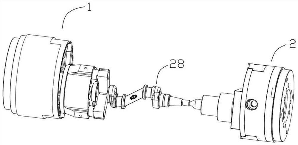
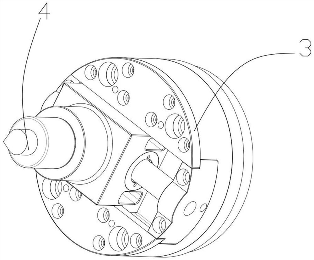
[0027] Such as figure 1 , figure 2 As shown, the present invention proposes an air compressor crank dual-head synchronous positioning and clamping device, which includes a clamping mechanism 1 and a positioning mechanism 2 that are oppositely arranged. The clamping mechanism 1 and the positioning mechanism 2 include hydraulically driven Mobile components 3, such as image 3 As shown, the function of the clamping mechanism 1 is to fix one end of the crank 28, and adjust the center position of the crank 28 according to the center of the disc to be processed. The function of the positioning mechanism 2 is to position the other end of the crank 28, and follow this The adjustment of the position of the clamping mechanism 1 is adjusted, so the clamping mechanism 1 and the positio...


PUM


Abstract

The invention provides an air compressor crank double-end synchronous positioning and clamping device. The device comprises a clamping mechanism and a positioning mechanism which are oppositely arranged, the clamping mechanism and the positioning mechanism comprise moving assemblies driven by oil pressure, a clamping jaw assembly is fixedly connected to the moving assembly of the clamping mechanism, an ejector pin is arranged on the moving assembly of the positioning mechanism, the clamping mechanism and the positioning mechanism are driven synchronously, the two ends of a workpiece can be positioned through the positioning mechanism and the clamping mechanism which are arranged respectively, meanwhile, oil can be fed synchronously to drive and adjust the position, it is guaranteed that the two ends act synchronously, in addition, the clamping mechanism is pushed through oil feeding in the middle, and compared with traditional end pushing, the adjusting stroke is greatly increased; andthe device can be used for larger workpieces, the size of the device is kept small, so that the device is suitable for small machine tools.

Description

technical field [0001] The invention relates to the field of machining equipment, in particular to a dual-head synchronous positioning and clamping device for an air compressor crank. Background technique [0002] The crankshaft is subjected to the joint action of the centrifugal force of the rotating mass, the periodically changing gas inertial force and the reciprocating inertial force, so that the crankshaft is subjected to the bending torsional load. [0003] Machining in the prior art is usually a cylindrical milling cutter to process workpieces, but when machining eccentric parts, it can only process a certain center position. When processing multiple eccentric workpieces, it needs to be continuously disassembly and assembly of the parts to be processed, but during the continuous disassembly and assembly process, the position of the parts will change uncontrollably, which will eventually lead to low processing accuracy of the parts and cannot meet the processing requir...

Claims


Application Information

Patent Timeline
Patent Type & Authority Applications(China)
IPC IPC(8): B23Q3/06
CPCB23Q3/062
Inventor 张瑞洋张文彪范福壮
Owner 昆山岱屹精密机械有限公司
Why Eureka
Try Eureka