Fin stabilizer lubricating system and lubricating operation method thereof

A technology of lubricating system and fin stabilization, applied in the directions of lubricating parts, engine lubrication, lubricating oil control valve, etc., can solve problems such as waste, difficulty in checking oil supply, reducing swing, etc., achieving simple operation and strong practicability , the effect of low cost

Inactive Publication Date: 2020-12-15
CSSC HUANGPU WENCHONG SHIPBUILDING COMPANY
View PDF7 Cites 2 Cited by
  • Summary
  • Abstract
  • Description
  • Claims
  • Application Information

AI Technical Summary

Problems solved by technology

[0002] The fin stabilizer is the most effective anti-roll device on the hull at present. It is installed in the bilge of the two sides of the ship. Force, thereby forming the anti-rolling moment, reducing the sway, so as to reduce the rolling of the hull, the fin stabilizer needs to change the fin angle as required when the hull is sailing, and the executive structure of the fin stabilizer needs to be lubricated with grease during operation. The fin stabilizer uses two oil pumps to supply oil to the stabilizer fins on the left and right sides respectively, and it cannot be supplied by a single oil pump. At the same time, if the oil supply pressure of the oil pump is too high, it will easily cause the outboard sealing cover of the fin stabilizer to deform and cause water leakage, and the oil supply It is difficult to check when there are too many, and it will cause waste

Method used


Image

  • Fin stabilizer lubricating system and lubricating operation method thereof

Examples


Embodiment Construction

[0013]The specific embodiments of the present invention will be described in further detail below in conjunction with the drawings and embodiments. The following examples are used to illustrate the present invention, but not to limit the scope of the present invention.

[0014]In the description of the present invention, it should be understood that the terms "installed", "connected", and "connected" used in the present invention should be understood in a broad sense, unless otherwise clearly specified and limited. For example, it may be a fixed connection or It can be a detachable connection or an integral connection; it can be a mechanical connection or an electrical connection; it can be directly connected or indirectly connected through an intermediate medium, and it can be the internal communication between two components. For those of ordinary skill in the art, the specific meanings of the above-mentioned terms in the present invention can be understood in specific situations.

[00...


PUM


Abstract

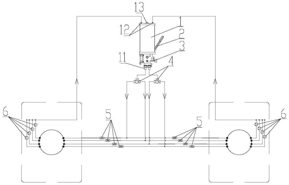
The invention discloses a fin stabilizer lubricating system. The fin stabilizer lubricating system comprises a hand pump, three-way valves, two-way valves and grease observers, wherein each three-wayvalve is provided with an inlet and two outlets; each two-way valve is provided with a switch; an oil outlet of the hand pump is connected with the inlet of each three-way valve through a pipeline; the two outlets of each three-way valve respectively communicate with oil injecting openings of a left fin stabilizer executing mechanism and a right fin stabilizer executing mechanism through three-waypipelines; the two-way valve is respectively arranged an oil injecting pipeline of the oil injecting opening of each of the left fin stabilizer executing mechanism and the right fin stabilizer executing mechanism; and an oil overflow opening of each of the left fin stabilizer executing mechanism and the right fin stabilizer executing mechanism is connected with the grease observer and a backflowpipeline. The fin stabilizer lubricating system has the advantages that the operation is simple; the practicability is high; grease can be injected into a plurality of lubricating positions of the left fin stabilizer executing mechanism and the right fin stabilizer executing mechanism only through one set of hand pump; in the operation process, only a three-way selection ball valve and a two-way ball valve on the corresponding pipeline need to be controlled; in addition, the risk of water leakage caused by deformation of an outboard sealing cover of the fin stabilizer due to excessive pump pressure can be avoided; and waste of lubricating grease cannot be caused.

Description

Technical field[0001]The invention relates to the technical field of ships, in particular to a fin stabilizer lubrication system and a lubrication operation method thereof.Background technique[0002]The fin stabilizer is currently the best anti-roll device on the hull. It is installed on the two sides of the ship's bilge. The section is wing-shaped, also called side rudder. The fin stabilizer is rotated by the control mechanism to make the water flow on. In order to reduce the rolling of the hull, the fin angle of the fin stabilizer must be changed as needed when the hull is sailing. The executive structure of the fin stabilizer needs to be lubricated by grease during operation. The fin is to use two oil pumps to supply grease to the fin stabilizers on the left and right sides. It cannot be supplied by a single oil pump. At the same time, if the oil supply pressure of the oil pump is too high, it will easily lead to the deformation of the fin stabilizer's outboard sealing cover and w...

Claims


Application Information

Patent Timeline
Patent Type & Authority Applications(China)
IPC IPC(8): F16N7/38F16N23/00F16N29/00B63B39/06
CPCB63B39/06F16N7/38F16N23/00F16N29/00F16N2210/06
Inventor 杨志虹林涛边泰刘禄鹏
Owner CSSC HUANGPU WENCHONG SHIPBUILDING COMPANY
Why Eureka
Try Eureka