An Informatics Computational Lithography Method

A technology of computational lithography and informatics, applied in the field of computational lithography of informatics, can solve the problems of unclear information transmission mechanism of lithography layout, and the theoretical limit of imaging accuracy of lithography system is not yet clear, so as to achieve the effect of improving convergence accuracy

Active Publication Date: 2021-06-08
BEIJING INSTITUTE OF TECHNOLOGYGY
View PDF4 Cites 0 Cited by
  • Summary
  • Abstract
  • Description
  • Claims
  • Application Information

AI Technical Summary

Problems solved by technology

However, researchers are still unclear about the informatics nature of computational lithography and the transmission mechanism of lithographic layout information in the framework of computational lithography. At the same time, the theoretical limit of the imaging accuracy of lithography systems that computational lithography algorithms can achieve is not yet clear. clear

Method used


Image

  • An Informatics Computational Lithography Method
  • An Informatics Computational Lithography Method
  • An Informatics Computational Lithography Method

Examples


Embodiment

[0115] Figure 4 401 in the figure is a circular light source, 402 is the target pattern 1, and 403 is the lithographic imaging obtained by irradiating the mask in 402 with the light source 401, and the imaging error is PE=6387. Taking a computational lithography method commonly used at present, that is, the SMO algorithm as an example, the light sources and masks in 401 and 402 are optimized using the SMO method. 406 is the lithographic imaging obtained by irradiating the mask in 405 with the light source in 404, and the imaging error is PE=1540.

[0116] Figure 5 501 is the circular light source, 502 is the target pattern 2, and 503 is the lithography image obtained by irradiating the mask in 502 with the light source in 501, and the imaging error is PE=3454. The light source and the mask in 501 and 502 are optimized by using the SMO method, and the obtained optimized light source is shown in 504 , and the optimized mask is shown in 505 . 506 is the lithographic imaging ...


PUM


Abstract

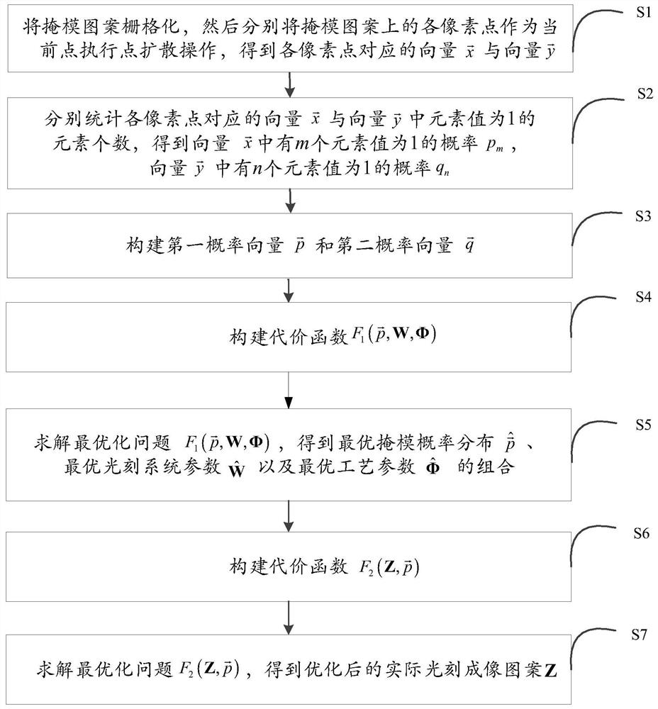
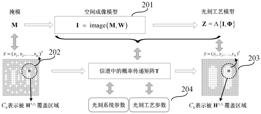
The invention provides an informatics calculation lithography method. Firstly, the channel model of computational lithography is established according to information theory, and then the optimal mask distribution, optimal lithography system parameters and process parameters under information theory are solved, and finally information theory is used to improve Calculate the convergence accuracy of the lithography algorithm; thus, the essence of the present invention is to describe the lithography system with a channel model, abstract the lithography imaging process as a channel transmission process, and regard mask graphics and lithography imaging as the input and For the output signal, the lithography system parameters and lithography process parameters are regarded as channel parameters that affect the transmission of lithography layout information, and the optimization of the mask by computational lithography is equivalent to the encoding process of the signal; that is to say, the present invention establishes The informatics model of computational lithography, through mathematical methods to study the information transmission mechanism and laws of lithography patterns, can obtain the theoretical limit of computational lithography imaging accuracy and improve the convergence accuracy of computational lithography algorithms.

Description

technical field [0001] The invention belongs to the field of microelectronics manufacturing and information technology, and in particular relates to an informatics calculation photolithography method. Background technique [0002] Photolithography is a key technology in the manufacture of integrated circuits. The photolithography system uses a short-wavelength light source to illuminate the mask on which the circuit pattern to be printed is pre-recorded. After the light passes through the mask, it is collected by the projection objective lens and projected onto the silicon wafer coated with photoresist. After exposure, development, etching and other processes, the circuit pattern is reproduced on the silicon wafer. [0003] However, the etching precision of a photolithography system will be affected by light diffraction, interference, and other optical effects and process variations. For this reason, computational lithography technology is widely used in the integrated cir...

Claims


Application Information

Patent Timeline
Patent Type & Authority Patents(China)
IPC IPC(8): G03F7/20G03F1/76
CPCG03F1/76G03F7/70216G03F7/70491
Inventor 马旭潘毅华
Owner BEIJING INSTITUTE OF TECHNOLOGYGY
Why Eureka
Try Eureka