Capacitive patch loaded dual-mode substrate integrated waveguide band-pass filter

A substrate-integrated waveguide and band-pass filter technology, applied in the microwave field, can solve the problem that the size cannot meet the application requirements, and achieve the effects of reducing the size, suppressing the outward radiation, and reducing the equivalent capacitance

Active Publication Date: 2020-12-15
郑州宇林电子科技有限公司
View PDF5 Cites 2 Cited by
  • Summary
  • Abstract
  • Description
  • Claims
  • Application Information

AI Technical Summary

Problems solved by technology

[0003] Using dual-mode substrate-integrated waveguide resonators to design microwave filters can achieve the goal of miniaturization, and dual-mode filters can achieve limited frequency transmission zeros, so it also has the advantage of high selectivity. Dual-mode substrate-integrated waveguide filters can The dual-mode fan-shaped substrate integrated waveguide resonator and the dual-mode square substrate integrated waveguide resonator are designed and implemented. Based on the above dual-mode substrate integrated waveguide filter, although a miniaturized and highly selective microwave bandpass filter can be realized , but for communication systems with stricter size requirements, the size still cannot meet the application requirements. In order to overcome the above deficiencies, a dual-mode substrate integration that is more miniaturized and capable of highly selective capacitive patch loading is proposed. waveguide bandpass filter

Method used


Image

  • Capacitive patch loaded dual-mode substrate integrated waveguide band-pass filter
  • Capacitive patch loaded dual-mode substrate integrated waveguide band-pass filter
  • Capacitive patch loaded dual-mode substrate integrated waveguide band-pass filter

Examples


Embodiment 1

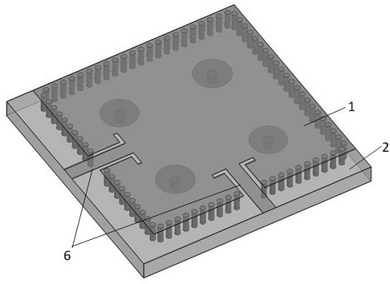
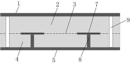
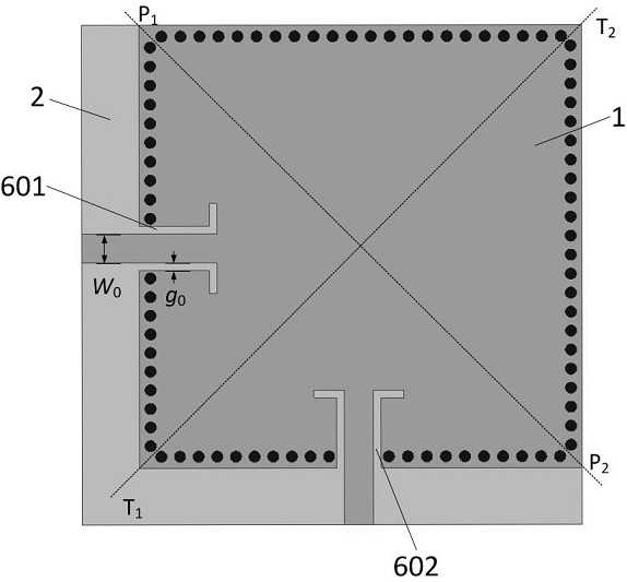
[0026] Such as Figure 1-4 As shown, a capacitive patch-loaded dual-mode substrate integrated waveguide bandpass filter includes a first layer of metal plate 1, a first layer of dielectric plate 2, and a second layer of metal plate 3 arranged in sequence from top to bottom , the second layer of dielectric plate 4 and the third layer of metal plate 5, and fixedly connected in turn, the thickness of the first layer of metal plate 1 and the third layer of metal plate 5 is 30 μm, the first layer of dielectric plate 2 and The model of the second layer of dielectric board 4 is Rogers5880, the thickness is 0.25mm, and the relative dielectric constant is 2.2. The surface of the first layer of metal plate 1 is provided with a microstrip to coplanar waveguide feeder structure 6, so The second layer metal plate 3 includes four capacitive patches 7, the third layer metal plate 5 is fully metal-covered ground, and the second layer dielectric plate 4 is provided with a metallized blind hole...

Embodiment 2

[0034] Such as Figure 1-4 As shown, a capacitive patch-loaded dual-mode substrate integrated waveguide bandpass filter includes a first layer of metal plate 1, a first layer of dielectric plate 2, and a second layer of metal plate 3 arranged in sequence from top to bottom , the second layer of dielectric plate 4 and the third layer of metal plate 5, and fixedly connected in turn, the thickness of the first layer of metal plate 1 and the third layer of metal plate 5 is 40 μm, the first layer of dielectric plate 2 and The model of the second layer of dielectric board 4 is Rogers5880, the thickness is 0.26mm, and the relative dielectric constant is 2.2. The surface of the first layer of metal plate 1 is provided with a microstrip to coplanar waveguide feeder structure 6, so The second layer metal plate 3 includes four capacitive patches 7, the third layer metal plate 5 is fully metal-covered ground, and the second layer dielectric plate 4 is provided with a metallized blind hole...

Embodiment 3

[0042] Such as Figure 1-4 As shown, a capacitive patch-loaded dual-mode substrate integrated waveguide bandpass filter includes a first layer of metal plate 1, a first layer of dielectric plate 2, and a second layer of metal plate 3 arranged in sequence from top to bottom , the second layer of dielectric plate 4 and the third layer of metal plate 5, and fixedly connected in turn, the thickness of the first layer of metal plate 1 and the third layer of metal plate 5 is 35 μm, the first layer of dielectric plate 2 and The model of the second layer of dielectric board 4 is Rogers5880, the thickness is 0.254mm, and the relative dielectric constant is 2.2. The surface of the first layer of metal plate 1 is provided with a microstrip to coplanar waveguide feeder structure 6, so The second layer metal plate 3 includes four capacitive patches 7, the third layer metal plate 5 is fully metal-covered ground, and the second layer dielectric plate 4 is provided with a metallized blind hol...


PUM

PropertyMeasurementUnit
Thicknessaaaaaaaaaa
Diameteraaaaaaaaaa
Widthaaaaaaaaaa

Abstract

The invention relates to a capacitive patch loaded dual-mode substrate integrated waveguide band-pass filter, which comprises a first layer metal plate, a first layer dielectric plate, a second layermetal plate, a second layer dielectric plate and a third layer metal plate which are arranged in sequence from top to bottom and are fixedly connected in sequence, wherein a microstrip-to-coplanar waveguide feed line structure is arranged on the surface of the first layer metal plate, the second layer metal plate comprises four capacitive patches, the third layer metal plate is an all-metal-covered ground, and a metallized blind hole is formed in the second layer dielectric plate. The top end of the metallized blind hole is fixedly connected with the bottom end of the capacitive patch, the bottom end of the metallized blind hole is fixedly connected with the top end of the all-metal covered ground, metal through holes which are communicated with each other are formed in the first layer dielectric plate and the second layer dielectric plate, and the metal through holes are communicated with the first layer metal plate and the third layer metal plate. The waveguide band-pass filter has the characteristics of more miniaturization and capability of realizing high selectivity.

Description

technical field [0001] The invention belongs to the field of microwave technology, and in particular relates to a dual-mode substrate integrated waveguide bandpass filter loaded by a capacitive patch. Background technique [0002] With the rapid development of wireless communication technology, wireless communication systems put forward higher and higher requirements for the weight, volume, integration and electrical performance of front-end circuits. Microwave filters, as frequency-selective devices, are widely used in front-end circuits of communication systems. Compared with microstrip resonators, substrate-integrated waveguide resonators have a higher quality factor, making substrate-integrated waveguide bandpass filters have smaller in-band insertion loss, so substrate-integrated waveguide filters are used in the front-end of communication systems It has been extensively studied and applied in circuits. [0003] Using dual-mode substrate-integrated waveguide resonators...

Claims


Application Information

Patent Timeline
IPC IPC(8): H01P1/20
CPCH01P1/20
Inventor 于海龙李春利
Owner 郑州宇林电子科技有限公司
Why Eureka
Try Eureka