Integrated Electric/Magnetic Alternating Wave Absorber and Antenna Array Multi-State Mutual Coupling Suppression Method

An integrated, state-of-the-art technology, applied in antenna coupling, antenna, electrical components and other directions, can solve the problems of large influence of antenna gain performance, affecting the overall function of communication, single working state, etc., to enhance mutual coupling suppression effect, simplify calculation complexity the effect of reducing additional cost

Active Publication Date: 2022-07-05
CHONGQING UNIV
View PDF15 Cites 0 Cited by
  • Summary
  • Abstract
  • Description
  • Claims
  • Application Information

AI Technical Summary

Problems solved by technology

With the development of related technologies, the mutual coupling problem of the patch antenna array has gradually become a key issue of the antenna system, and the reduction of the radiation performance caused by the mutual coupling of the array will greatly affect the overall function of the communication
When the array works in phased beam scanning, the mutual coupling problem in the scanning state is more complicated than that of the traditional array, which brings greater challenges to mutual coupling suppression
In the existing mutual coupling suppression technology, the method of using material-type wave-absorbing loading has problems such as complicated installation, high cost, and great impact on the antenna gain performance; while the use of filtering structures will affect the standing wave performance of the antenna, and cannot Adapt to the phased array beam scanning state; using the traditional structural absorbing loading method, its working state is single, and it can only achieve mutual coupling suppression during certain specific beam scanning

Method used


Image

  • Integrated Electric/Magnetic Alternating Wave Absorber and Antenna Array Multi-State Mutual Coupling Suppression Method
  • Integrated Electric/Magnetic Alternating Wave Absorber and Antenna Array Multi-State Mutual Coupling Suppression Method
  • Integrated Electric/Magnetic Alternating Wave Absorber and Antenna Array Multi-State Mutual Coupling Suppression Method

Examples


Embodiment Construction

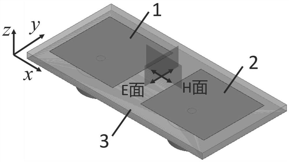
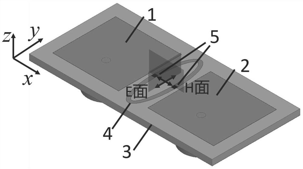
[0032] The present invention will be further described below with reference to the accompanying drawings and specific embodiments. A specific embodiment of the present invention is as follows figure 1 As shown, in the embodiments of the integrated electric / magnetic alternating wave absorbing device and the multi-state mutual coupling suppression method of the antenna array of the present invention, the antenna array is arranged along the x direction (H plane) and consists of the same radiating elements 1 and 2 . The radiation unit is in the form of a back-feed patch antenna. The radiation patch is printed on the upper copper clad surface of the dielectric substrate 3 , and the metal backplane is printed on the lower copper clad surface of the dielectric substrate 3 . The antenna is polarized in the y direction. The array works in three working states: non-scanning, differential beam and general beam scanning. The length of the transmission line of the feed source is used to c...


PUM


Abstract

The invention discloses an integrated electric / magnetic alternating wave absorbing device and an antenna array multi-state mutual coupling suppression method. The method achieves significant suppression of mutual coupling of the H-plane phased array in multiple working states such as non-scanning / arbitrary beam scanning / differential beams through the design of the working mode and structural parameters of the absorbing structure. Compared with the electromagnetic isolation method of the frequency selective device, the suppression method has little interference to the operating frequency, standing wave and pattern of the antenna array; The radiation efficiency and gain performance of the antenna have little influence; compared with the conventional absorbing design, which can only suppress the coupling of a specific antenna working state, the electromagnetic / magnetic alternating absorption design can effectively reduce the coupling of the antenna in various working states. The resistance-loaded elliptical metal ring structure adopted in the present invention realizes the mutual coupling suppression of the array and the maintenance of the radiation performance of the array at the same time by designing its positional relationship with the antenna electric field / current extreme value. The wave absorbing structure utilizes the electric / magnetic alternate absorption design, so that the antenna array can effectively suppress the mutual coupling under the complex working state of arbitrary beam scanning.

Description

technical field [0001] The invention relates to the field of antennas (H05B6 / 72), in particular to an integrated electric / magnetic alternating wave absorbing device and a method for suppressing multi-state mutual coupling of an antenna array. Background technique [0002] Antenna mutual coupling suppression technology is an important research content of antenna arrays. It reduces the mutual coupling between array antenna elements by means of filtering, absorbing waves or metal isolation. Among many antenna forms, patch antennas are widely used in electromagnetic wave transceiver modules of communication systems due to their many advantages. Especially in high-speed communication systems such as 5G, patch arrays have become the main form of antenna function. With the development of related technologies, the mutual coupling problem of the patch antenna array has gradually become a key problem of the antenna system, and the reduction of the radiation performance caused by the m...

Claims


Application Information

Patent Timeline
Patent Type & Authority Patents(China)
IPC IPC(8): H01Q17/00H01Q1/38H01Q1/52
CPCH01Q1/52H01Q1/38H01Q17/007
Inventor 孙志伟曹海林龚鹤凌刘润
Owner CHONGQING UNIV
Why Eureka
Try Eureka