[0022]In the description of the present invention, it should be understood that the terms "center", "longitudinal", "transverse", "upper", "lower", "front", "rear", "left", "right", " The orientation or positional relationship indicated by "vertical", "horizontal", "top", "bottom", "inner", "outer" etc. is based on the orientation or positional relationship shown in the drawings, and is only for the convenience of describing the present invention and The description is simplified, rather than indicating or implying that the pointed device or element must have a specific orientation, be constructed and operated in a specific orientation, and therefore cannot be understood as a limitation of the present invention. In addition, the terms "first", "second", etc. are only used for descriptive purposes, and cannot be understood as indicating or implying relative importance or implicitly indicating the number of indicated technical features. Therefore, the features defined with "first", "second", etc. may explicitly or implicitly include one or more of these features. In the description of the present invention, unless otherwise specified, "plurality" means two or more.
[0023]In the description of the present invention, it should be noted that the terms "installed", "connected" and "connected" should be understood in a broad sense, unless otherwise clearly specified and limited. For example, they can be fixed or detachable. Connected or integrally connected; it can be a mechanical connection or an electrical connection; it can be directly connected or indirectly connected through an intermediate medium, and it can be the internal communication between two components. For those of ordinary skill in the art, the specific meanings of the above terms in the present invention can be understood through specific situations.
[0024]The technical solutions in the embodiments of the present invention will be clearly and completely described below in conjunction with the accompanying drawings in the embodiments of the present invention. Obviously, the described embodiments are only a part of the embodiments of the present invention, rather than all the embodiments. Based on the embodiments of the present invention, all other embodiments obtained by those of ordinary skill in the art without creative work shall fall within the protection scope of the present invention.
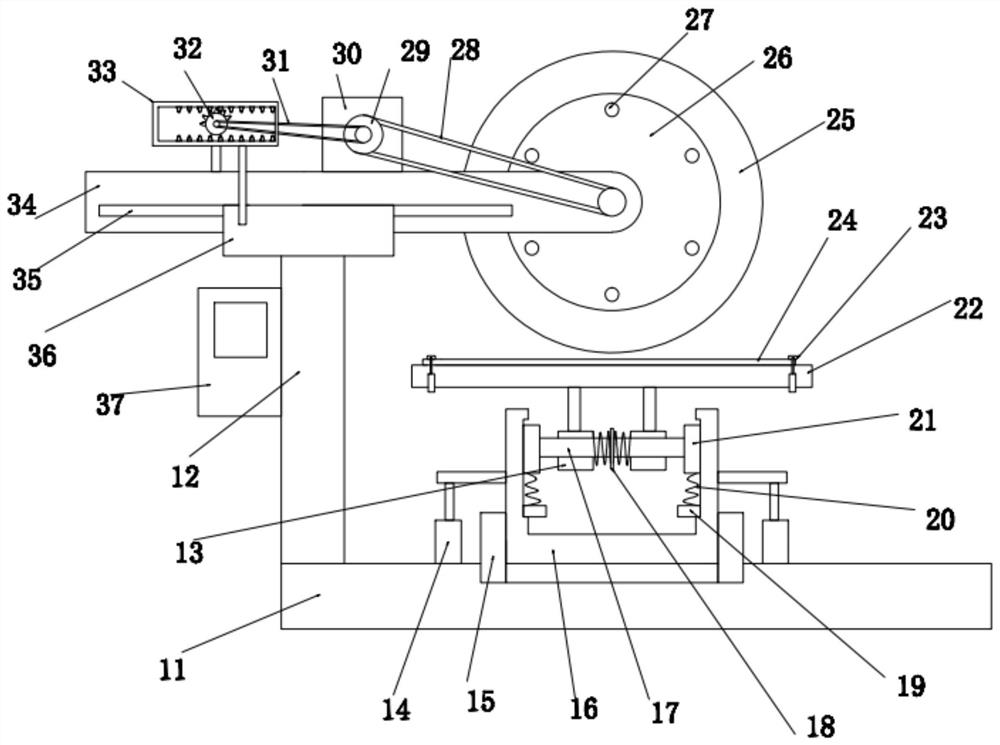
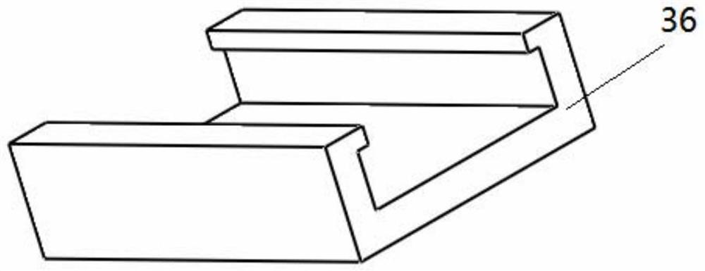
[0025]SeeFigure 1-3 In the embodiment of the present invention, a sandpaper polishing detection device for tire force and moment detection includes a base 11 for supporting the ground. A support column 12 is vertically arranged at the upper left end of the base 11, and the upper end of the support column 12 A guide block 36 is provided. A moving seat 34 is slidably fitted in the U-shaped chute at the upper end of the guide block 36. The inner wall of the U-shaped groove of the guide block 26 is provided with a guide groove 35 embedded in the surface of the movable seat 34 In the internal limit block, one end of the moving seat 34 is equipped with a grinding wheel mechanism for grinding the sandpaper 24, and the upper end of the base 11 is equipped with a positioning assembly for placing the sandpaper 24. The positioning assembly is electrically Connect to the control panel 37 arranged on the support column 12;
[0026]The grinding wheel mechanism is drivingly connected to a driving disc 29 through a first belt 28, and the driving disc 29 is installed at the output end of the driving motor 30;
[0027]The moving seat 34 is also provided with a reciprocating driving member for driving the grinding wheel mechanism to move left and right to realize the pre-sanding operation on the entire surface of the sandpaper 24;
[0028]The reciprocating drive member includes at least one transmission rod arranged on the side of the guide block 36, a transmission frame 33 is provided at the upper end of the transmission rod, and a gear bar is respectively arranged on the upper and lower sides of the transmission frame 33. A half gear 32 is fitted inside the transmission frame 33. One end of the fixed shaft of the half gear 32 is connected to a fixed seat on the moving seat 34, and the transmission pulley on the side of the half gear 32 is connected to a second belt 31 through a second belt 31. The drive disc 29 at the output end of the drive motor 30 is in transmission connection. Under the transmission of the second belt 31, the half gear 32 will rotate inside the transmission frame 33, and when it meshes with the gear bar on the upper side of the transmission frame 33, it will drive the movement seat 34 along Sliding on one side of the guide block 36, when meshed with the gear bar on the lower side of the transmission frame 33, the moving seat 34 will slide along the other side of the guide block 36, so that the grinding wheel mechanism can reciprocate on the surface of the sandpaper 24 Polished
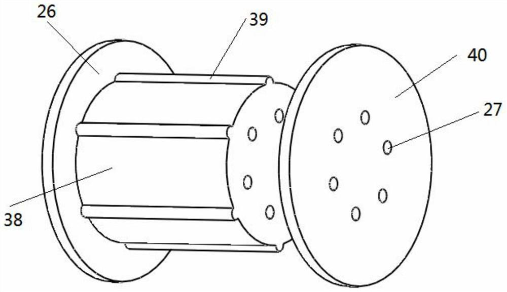
[0029] The grinding wheel mechanism includes a grinding wheel 25. The center of the grinding wheel 25 is provided with a mounting hole for the positioning post 38 to pass through. The inner wall of the mounting hole is provided with a groove that fits with the limiting protrusion 39 on the surface of the positioning post 38. The end of the positioning column 38 is provided with a first pressure plate 26 for pressing one end surface of the grinding wheel 25, and the other end of the positioning column 38 is matched with a second pressure plate 40 for pressing the other end surface of the grinding wheel 25. Both the second pressure plate 40 and the positioning column 38 are provided with a number of positioning holes 27 for the installation of bolts, so that during installation, the first pressure plate 26 and the second pressure plate 40 can be used to make the grinding wheel It is tightly fixed on the positioning column 38 to realize the assembly of the grinding wheel mechanism.
[0030]The positioning assembly includes a lifting fixing sleeve 15 arranged on the upper end of the base 11. The lifting fixing sleeve 15 is slidably fitted with a lifting fixing column 16, and the left and right sides of the lifting fixing column 16 are symmetrically provided with side blocks. Block connection is used to drive the lifting push rod 14 to move up and down to adjust the distance between the sandpaper 24 and the grinding wheel 25. Above the lifting fixed column 16 is provided a fixed platform 22 for placing the sandpaper 24. The left and right ends of the fixed platform 22 are symmetrical. There is a clamping and positioning member 23 for positioning the sandpaper 24, and a buffer connecting member for detecting the pressure and friction force of the sandpaper 24 when the sandpaper 24 is polished is provided between the lifting fixed column 16 and the fixed platform 22, so that the The friction coefficient is calculated;
[0031]The buffer connecting piece includes a mounting cavity opened at the upper end of the lifting fixed column 16, the left and right inner walls of the mounting cavity are symmetrically provided with lifting slide grooves, each lifting slide groove is fitted with a longitudinal slider 21, two longitudinal slides on the left and right At least one cross-bar 17 is erected between the blocks 21, a first force-measuring block 18 is provided in the middle of the cross-bar 17, and a sliding sleeve 13 is slidably fitted on the cross-bars 17 on both sides of the first force-measuring block 18 , The upper side of the sliding sleeve 13 and the fixed platform 22 are connected and fixed by struts, the sliding sleeve 13 and the first force measuring block 18 are connected by a horizontal buffer spring, and the lower end of the longitudinal slider 21 is connected by a buffer spring 20 is connected and fixed with the second force measuring block 19, the first force measuring block 18 is used to detect the friction force generated by the grinding wheel 25 when grinding the sandpaper 24, and the second force measuring block 19 detects the downward movement of the grinding wheel 25 on the sandpaper 24. pressure;
[0032]It should be noted that the weight detected by the second force measuring block 19 includes the weight of the equipment and the weight of the sandpaper itself, so the zero adjustment operation is required before the detection;
[0033]The friction coefficient here is equal to the friction force divided by the pressure. The control panel 37 is also provided with an alarm. When it is detected that the friction coefficient maintains a constant value, the alarm works to remind the staff to complete the pre-grinding;
[0034]The clamping and positioning member 23 includes a pressing rod arranged on the outside of the fixing table 22, and the output end of the pressing rod is connected to a pressing bar for pressing the sandpaper 24 on the fixing table 22, and the pressing rod is driven to move downward through the pressing rod That is, the sandpaper 24 can be pressed tightly on the fixing table 22 to realize the fixing of the sandpaper 24;
[0035]The working principle of the present invention is: when in use, the sandpaper 24 is first placed on the fixed table 22, fixed by clamping the positioning member 23, and then the pressure between the sandpaper 24 and the grinding wheel 25 is adjusted as needed, and then the drive motor 30 Drive the grinding wheel mechanism to rotate, so that the grinding wheel 25 grinds on the surface of the sandpaper 24. Under the action of the reciprocating drive, the grinding wheel mechanism will reciprocate on the surface of the sandpaper 24 to ensure the uniformity of the grinding. When grinding, the friction force The sliding sleeve 13 will slide horizontally along the cross bar 17, thereby generating a pressure or friction force on the first force measuring block 18. The second force measuring block 19 will detect the pressure of the grinding wheel mechanism on the sandpaper 24, and the control panel 37 will follow The received data calculates the friction coefficient. When the friction coefficient reaches a constant value, the alarm will send out an alarm signal.
[0036]For those skilled in the art, it is obvious that the present invention is not limited to the details of the foregoing exemplary embodiments, and the present invention can be implemented in other specific forms without departing from the spirit or basic characteristics of the present invention. Therefore, from any point of view, the embodiments should be regarded as exemplary and non-limiting. The scope of the present invention is defined by the appended claims rather than the above description, and therefore it is intended to fall within the claims. All changes within the meaning and scope of equivalent elements of are included in the present invention. Any reference signs in the claims should not be regarded as limiting the claims involved.
[0037]In addition, it should be understood that although this specification is described in accordance with the implementation manners, not each implementation manner only includes an independent technical solution. This narration in the specification is only for clarity, and those skilled in the art should consider the specification as a whole The technical solutions in the embodiments can also be appropriately combined to form other implementations that can be understood by those skilled in the art.