A kind of bilateral feedback control method and bilateral feedback device
A feedback control, bilateral technology, applied in control/regulation systems, output power conversion devices, instruments, etc., can solve the problem of burning out the secondary circuit synchronous switch tube, the optocoupler current limiting resistance should not be too large, and cannot work stably, etc. problem, to achieve the effect of improving dynamic response, reducing no-load power consumption, and reducing power consumption
- Summary
- Abstract
- Description
- Claims
- Application Information
AI Technical Summary
Problems solved by technology
Method used
Image
Examples
Embodiment 1
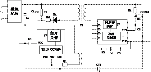
[0073] Please refer to Figure 5 , this embodiment proposes a logic control method for bilateral feedback, which can be applied to the above-mentioned bilateral feedback architecture DSR, and the method includes:
[0074] S110, the primary controller judges the timing stage of the circuit according to the voltage change on the transformer winding.
[0075] Exemplarily, with figure 1 Taking the bilateral feedback architecture shown as an example, the primary controller can obtain the voltage change of the transformer by collecting the voltage signal on the winding on the primary side of the transformer in real time. Furthermore, the primary controller performs circuit sequence judgment according to the voltage change signal, so as to know which stage the transformer sequence is currently in.
[0076] It can be understood that no matter whether it is the main switching tube Q1 or the synchronous switching tube Q7, as long as the switching tube is turned on or off, the magnetic...
Embodiment 2
[0127] Please refer to Figure 13 and Figure 14 , this embodiment also proposes a bilateral feedback logic control method, which is applied to the above-mentioned bilateral feedback architecture. The difference from Embodiment 1 is that the bilateral feedback control method of this embodiment is mainly based on the voltage change signal of the secondary circuit The primary reference voltage (the reference voltage of FB1 / FB2) in the primary circuit loop is adjusted, so as to realize the control of the main switching tube. This method can realize variable voltage output, especially fast response in technologies such as fast charging.
[0128] Exemplarily, after power-on, the primary controller controls the bilateral feedback architecture to enter the primary feedback control mode to establish the initial operating voltage required by the circuit, and after the initial operating voltage is established, the secondary controller passes the secondary feedback terminal Obtain the ou...
Embodiment 3
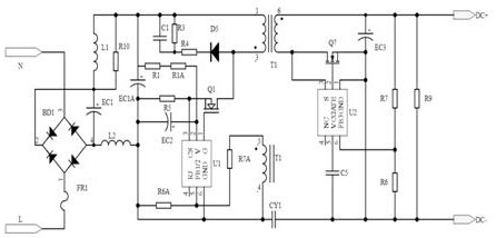
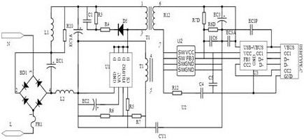
[0145] Please refer to figure 1 , this embodiment proposes a bilateral feedback device, exemplary, such as figure 2 As shown, the bilateral feedback device can adopt the method of the above-mentioned embodiment 1 or 2 for circuit logic control. Optionally, as in image 3 As shown, the bilateral feedback device also includes a fast charging circuit connected to the secondary output. At this time, the secondary circuit needs to meet the variable voltage output function. Among them, the fast charging circuit will support the fast charging protocol. If the fast charging mode is required, the secondary controller of the secondary circuit can change the voltage to meet the voltage or current required for fast charging; if the non-fast charging mode is used , then the secondary circuit can also step down to normal charging mode and so on. In one embodiment, the fast charging circuit can be integrated in the same chip with devices such as the primary controller and the synchronous...
PUM
 Abstract
Description
Claims
Application Information
 - R&D
- Intellectual Property
- Life Sciences
- Materials
- Tech Scout
- Unparalleled Data Quality
- Higher Quality Content
- 60% Fewer Hallucinations
Browse by: Latest US Patents, China's latest patents, Technical Efficacy Thesaurus, Application Domain, Technology Topic, Popular Technical Reports.
© 2025 PatSnap. All rights reserved.Legal|Privacy policy|Modern Slavery Act Transparency Statement|Sitemap|About US| Contact US: help@patsnap.com


