Eureka AIR delivers breakthrough ideas for toughest innovation challenges, trusted by R&D personnel around the world.

Ultrasound neuromodulation techniques

A technology of ultrasound and regulation system, applied in the field of neuromodulation

Pending Publication Date: 2020-12-18
GENERAL ELECTRIC CO
View PDF0 Cites 1 Cited by
  • Summary
  • Abstract
  • Description
  • Claims
  • Application Information

AI Technical Summary

Problems solved by technology

However, positioning electrodes at or near target nerves is challenging
For example, such techniques may involve the surgical placement of electrodes that deliver energy
Furthermore, targeting specific tissues via neuromodulation is challenging

Method used


Image

  • Ultrasound neuromodulation techniques
  • Ultrasound neuromodulation techniques
  • Ultrasound neuromodulation techniques

Examples


Embodiment

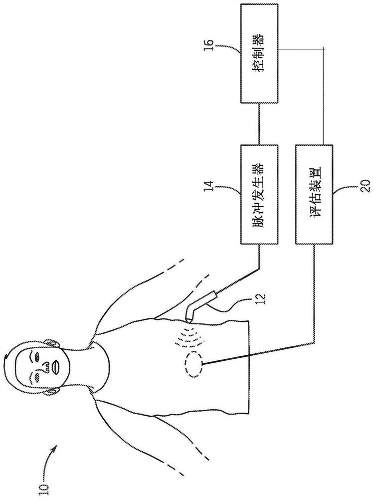
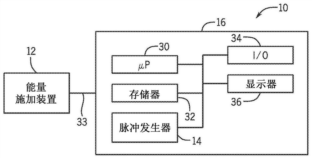
[0137] Figure 7 is a block diagram of a system 10 including an energy application device 12 and a pulse generator 14 configured to apply high intensity focused ultrasound (HIFU). In one embodiment, system 10 includes a pulse generator including, for example, a function generator 80 , a power amplifier 82 and a matching network 84 . In one embodiment used to generate experimental results as provided herein, the pulse generator includes a 1.1 MHz High Intensity Focused Ultrasound (HIFU) transducer (Sonic Concepts H106), matching network (e.g., Sonic Concepts), RF power amplifier (ENI 350L) and function generator (Agilent33120A). In the example shown, the 70-mm diameter HIFU transducer has a spherical surface with a radius of curvature of 65 mm and a 20-mm diameter hole in the middle into which the imaging transducer is inserted. The depth of focus of the transducer is 65mm. The full width of the numerically simulated pressure curve at half-amplitude is 1.8 mm in lateral dire...


PUM


Abstract

The subject matter of the present disclosure generally relates to techniques for neuromodulation of a tissue that include applying energy (e.g., ultrasound energy) into the tissue to cause altered activity at a synapse between a neuron and a non-neuronal cell. In one embodiment, the energy is applied to cause persistent effects as a result of repeated application of energy within a predefined treatment window.

Description

technical field [0001] The subject matter disclosed herein relates to neuromodulation, and more particularly to techniques for modulating physiological responses using energy applied from an energy source. Background technique [0002] Neuromodulation has been used to treat a variety of clinical conditions. For example, electrical stimulation of various parts along the spinal cord has been used to treat chronic back pain. Such treatments can be delivered by implantable devices that periodically generate electrical energy that is applied to tissue to activate certain nerve fibers, which in turn may lead to a reduction in pain sensation. In the case of spinal cord stimulation, the stimulating electrodes are usually located in the epidural space, although the pulse generator may be positioned slightly away from the electrodes, such as in the abdominal or gluteal region, but connected to the electrodes by wires. In other embodiments, deep brain stimulation can be used to stimu...

Claims


Application Information

Patent Timeline
Patent Type & Authority Applications(China)
IPC IPC(8): A61N1/36A61N7/00
CPCA61N1/36034A61N7/00A61N7/02A61N2007/0026A61N2007/0052
Inventor 克里斯托弗·迈克尔·普莱奥维多利亚·尤金妮亚·科特罗
Owner GENERAL ELECTRIC CO
Why Eureka
Eureka Blog
Learn More