Drive circuit, electronic device, and method for controlling charging

A technology for driving circuits and electronic equipment, applied in the fields of driving circuits, electronic equipment and control charging, can solve the problems of reduced fast charging current, reduced charging efficiency, large MOS tube impedance, etc., so as to improve the driving voltage and avoid the reduction of charging efficiency. Effect

Active Publication Date: 2022-08-09
GUANGDONG OPPO MOBILE TELECOMM CORP LTD
View PDF5 Cites 0 Cited by
  • Summary
  • Abstract
  • Description
  • Claims
  • Application Information

AI Technical Summary

Problems solved by technology

[0003] When fast charging electronic equipment, the gate voltage of the field effect (Metal Oxide Semiconductor, MOS) tube on the fast charging circuit is controlled by the driving voltage output by the driving circuit at present, but the driving voltage output by the driving circuit currently used is relatively low. Small, so that the impedance between the drain and the source of the MOS tube is large when it is turned on. On the one hand, it causes serious heating of the MOS tube and reduces the charging efficiency; The impedance of the charging circuit is too large, which reduces the fast charging current or exits the fast charging mode

Method used


Image

  • Drive circuit, electronic device, and method for controlling charging
  • Drive circuit, electronic device, and method for controlling charging
  • Drive circuit, electronic device, and method for controlling charging

Examples


Embodiment Construction

[0035] The technical solutions in the embodiments of the present application will be described below with reference to the accompanying drawings in the embodiments of the present application. Obviously, the described embodiments are part of the embodiments of the present application, not all of the embodiments. Based on the embodiments in this application, all other embodiments obtained by those of ordinary skill in the art without creative efforts shall fall within the protection scope of this application.

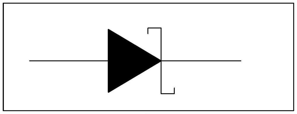
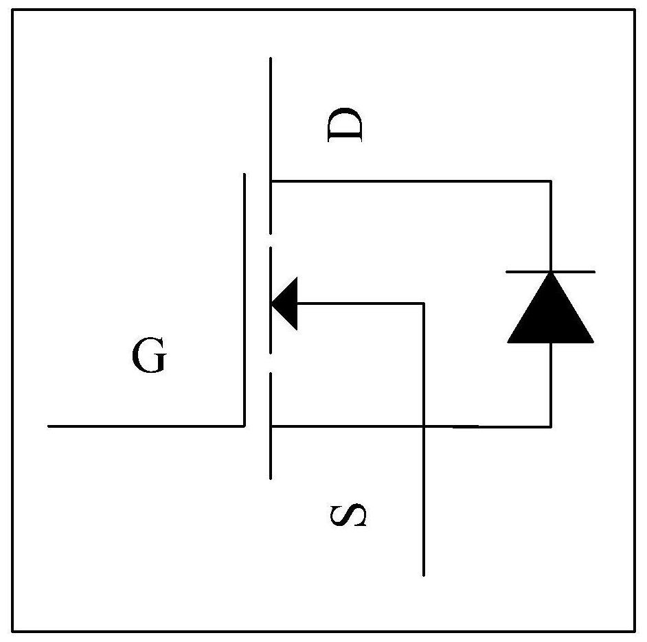
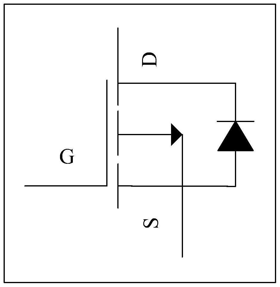
[0036] In order to understand the present application more clearly, the working principles of the diodes and the MOS transistors in the embodiments of the present application are briefly introduced first, so as to facilitate the subsequent understanding of the solutions of the present application. However, it should be understood that the content introduced below is only for a better understanding of the present application, and should not be specifically limited to the pr...


PUM


Abstract

The present application provides a driving circuit, an electronic device and a charging control method, including: a first interface connected to an external power supply device for receiving a DC signal input by the external power supply device; a second interface connected to the MCU connection, for receiving at least two pulse width modulation PWM signals input by the MCU; processing circuit, respectively connected with the first interface and the second interface, for connecting the direct current signal and the at least two channels The PWM signal is superimposed and rectified to obtain a first direct current signal, and the first direct current signal is output to the gate of the MOS transistor, so that the voltage of the gate of the MOS transistor is greater than the first threshold. Since the MCU inputs at least two PWM signals to the driving circuit through the second interface, it can avoid the reduction of the charging efficiency, the reduction of the fast charging current or the exit of the fast charging mode due to the low voltage of the MOS transistor VGS.

Description

technical field [0001] The embodiments of the present application relate to the technical field of charging, and in particular, to a driving circuit, an electronic device, and a method for controlling charging. Background technique [0002] With the popularization of electronic devices (such as mobile phones, pads, wristbands, etc.), the functions of electronic devices are constantly enriched. Some manufacturers have launched electronic devices that support fast charging mode. Fast charging technology has greatly shortened the charging time of electronic devices. widely favored. [0003] When fast charging electronic equipment, the gate voltage of the field effect (Metal Oxide Semiconductor, MOS) tube on the fast charging circuit is currently controlled by the driving voltage output by the driving circuit. However, the driving voltage output by the driving circuit currently used is relatively Small, so that the impedance between the drain and source of the MOS tube when it ...

Claims


Application Information

Patent Timeline
Patent Type & Authority Patents(China)
IPC IPC(8): H02J7/04
CPCH02M3/156H02J7/00711H02P27/08H03F3/2171H03K7/08
Inventor 刘绍斌田晨卜昌军张俊
Owner GUANGDONG OPPO MOBILE TELECOMM CORP LTD
Why Eureka
Try Eureka