
Carbon dioxide trapping system and method based on blast furnace slag flushing water waste heat recycling

A blast furnace slag flushing water and carbon dioxide technology, which is applied in the field of blast furnace heat energy recovery, can solve the problems of increasing carbon capture cost, reboiler consuming large steam or electric energy, etc., to ensure continuous stability of heating supply, reduce energy consumption burden, The effect of reducing energy consumption for regeneration

Pending Publication Date: 2020-12-25
ANHUI UNIVERSITY OF TECHNOLOGY
View PDF5 Cites 10 Cited by
  • Summary
  • Abstract
  • Description
  • Claims
  • Application Information

AI Technical Summary

Problems solved by technology

[0004] In the traditional chemical absorption carbon capture system, the regeneration temperature of the solution in the desorption tower must be maintained at 100°C to 120°C, which requires the reboiler to consume a large amount of steam or electricity, which increases the cost of carbon capture and becomes a constraint for CO 2 Key factors for large-scale application of capture technologies across emission sources

Method used


Image

  • Carbon dioxide trapping system and method based on blast furnace slag flushing water waste heat recycling
  • Carbon dioxide trapping system and method based on blast furnace slag flushing water waste heat recycling
  • Carbon dioxide trapping system and method based on blast furnace slag flushing water waste heat recycling

Examples


Embodiment

[0042] Table 1 Composition of blast furnace gas

[0043]

[0044] In this implementation case, the carbon dioxide capture and separation system of the present invention is used to separate carbon dioxide from blast furnace gas (gas temperature 40°C, carbon dioxide content 20%).

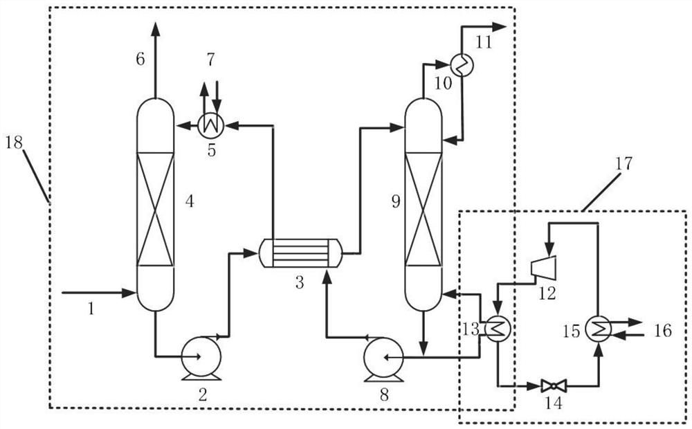
[0045] The carbon dioxide capture and separation system includes blast furnace gas 1, purified gas 6, absorption tower 4, desorption tower 9, lean liquid pump 8, rich liquid pump 2, lean liquid heat exchanger 3, lean liquid condenser 5, Gas-liquid separator 10, reboiler. The dust-removed, desulfurized and denitrified blast furnace gas 1 enters the absorption tower 4 from bottom to top to contact with the lean liquid absorbent sprayed from top to bottom in the absorption tower, and the gas-liquid two-phase separation takes place on the packing surface. Heat and mass transfer, so that the CO in the lean liquid and blast furnace gas 1 2 A chemical reaction occurs, and most of the CO in blast furnace...


PUM


Abstract

The invention discloses a carbon dioxide trapping system and method based on blast furnace slag flushing water waste heat recycling. The carbon dioxide trapping system comprises a carbon dioxide trapping and separating system and a heat pump system. The carbon dioxide capture and separation system comprises an absorption tower, a desorption tower, a barren liquor pump, a rich liquor pump, a barrenand rich liquor heat exchanger and a barren liquor condenser; the carbon dioxide capturing and separating system is connected with the heat pump system through a reboiler / condenser, the reboiler / condenser comprises a reboiler and a condenser, the reboiler is communicated with the carbon dioxide capturing and separating system, and the condenser is communicated with the heat pump system; the blastfurnace gas is treated by adopting a chemical absorption method with the advantages of good trapping effect, strong treatment air volume, mature process and the like, so that the carbon emission coefficient of the blast furnace gas can be reduced under the condition that the CO2 removal rate of the blast furnace gas is 90 percent, and the heat value of the blast furnace gas can be increased fromabout 3500kJ / Nm < 3 > to about 4400kJ / Nm < 3 >.

Description

technical field [0001] The invention relates to the technical field of blast furnace heat energy recovery, in particular to a carbon dioxide capture system and method based on recovery and utilization of waste heat from blast furnace slag flushing water. Background technique [0002] At present, the blast furnace gas discharged during the domestic ironmaking process is used for residual pressure power generation after being treated by the dust collector, and then enters the hot blast stove or other kilns as heating fuel; the slag washing water used to wash the slag produced in the ironmaking process is directly After heat exchange in the cooling tower, the blast furnace slag is recycled and washed again. Therefore, in the process of recycling blast furnace gas, due to the large carbon emission coefficient and inert gas content, low combustion calorific value, low combustion temperature, difficulty in ignition and poor combustion stability, and the waste heat of blast furnace...

Claims


Application Information

Patent Timeline
IPC IPC(8): C10K1/10C10K1/12C10K1/14B01D53/78B01D53/96B01D53/62C01B32/50
CPCB01D53/62B01D53/78B01D53/96B01D2257/504C10K1/005C10K1/10C10K1/12C10K1/121C10K1/143C01B32/50Y02B30/52Y02P20/129Y02P20/151Y02C20/40
Inventor 黄志甲张金星张样黄战鲁月红祝立萍
Owner ANHUI UNIVERSITY OF TECHNOLOGY
Learn More