Linear actuator

A technology of linear actuators and drive motors, which is applied to electric components, transmission devices, and mechanical energy control, etc., can solve the problems of poor actuator transmission efficiency, increased joint cost, and high noise, and achieves simple and convenient changes in stroke and connection methods. Ease of use and the effect of prolonging the life of the lead screw

Active Publication Date: 2020-12-25
CHANGZHOU KAIDI ELECTRICAL INC
View PDF8 Cites 1 Cited by
  • Summary
  • Abstract
  • Description
  • Claims
  • Application Information

AI Technical Summary

Problems solved by technology

Chinese patent document CN207518427U discloses a linear actuator, the worm wheel and the screw are independently designed, but the worm is still centered on the screw, and the worm is centered on the housing, it is difficult to ensure the concentricity of the screw and the worm Keep consistent on the above, due to the shaking during the movement of the screw, it will lead to poor meshing accuracy of the worm gear, causing problems such as poor transmission efficiency, high noise and short life of the actuator
The disadvantages of this connection structure are: (1) increase the cost of the butt joint; (2) first fix the connection between the conduit and the conduit by screwing the screw and the bolt groove, and then install the shell through the screw, which requires tools and cumbersome procedures for fixing; (3) In order to avoid assembly errors, the shell and conduit sections need to be fool-proof

Method used


Image

  • Linear actuator
  • Linear actuator
  • Linear actuator

Examples


Embodiment 1)

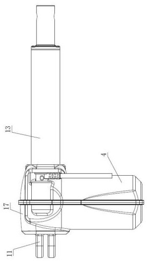
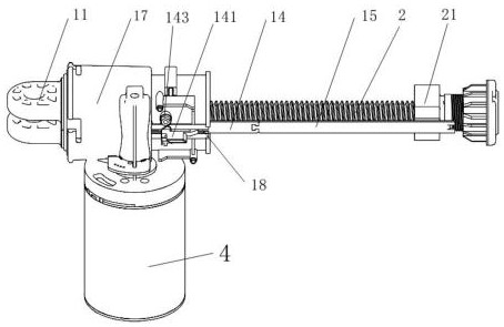
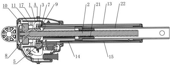
[0049] See Figure 1 to Figure 7, the present invention provides a linear actuator, including a main housing 1, a screw 2, a worm wheel 3, a drive motor 4 and a worm 5, the power output of the drive motor 4 is a worm 5, the worm 5 meshes with the worm wheel 3, and the worm wheel 3. There is a hole in the core part of the threaded mandrel 2 and the gear teeth of the outer ring meshing with the worm 5. A mounting circumferential surface 301 is provided on the contour surface of the worm gear between the hole and the gear teeth. The main housing 1 is provided with There is a centering circumferential surface 101 adapted to the installation circumferential surface 301, and the installation circumferential surface 301 and the centering circumferential surface 101 only need to be adapted, and only one is an inner cylindrical surface and the other is an outer cylindrical surface, and the worm gear 3 is installed by The circumferential surface 301 and the centering circumferential sur...

Embodiment 2)

[0063] Compared with Embodiment 1, this embodiment is equipped with a screw shaft sleeve 8 through a spline 16 at the rear of the screw shaft 2, and the inner ring of the worm wheel 3 is sleeved on the front portion of the screw shaft sleeve 8 through a key 9. 3 is in clearance fit with the screw shaft sleeve 8, and the screw shaft 2 and the worm gear 3 are fixed through the screw shaft sleeve 8, so as to avoid the tight fit between the worm gear 3 and the screw shaft 2, and prevent the worm gear 3 from directly pressing on the screw shaft 2 to cause the screw The rod 2 is bent to ensure the linearity of the screw rod 2 .

[0064] A bearing 10 is installed at the rear of the screw shaft sleeve 8, the rear end of the screw mandrel 2 is provided with an external thread, and the fastening nut 6 with internal thread is engaged with the external thread of the screw mandrel 2, and the front end surface of the fastening nut 6 is in contact with the external thread of the screw mandrel...


PUM


Abstract

The invention discloses a linear actuator. The linear actuator comprises a main shell, a lead screw, a worm wheel, a driving motor and a worm, wherein a mounting circumferential surface is arranged onthe contour surface of the worm wheel between a hole of a core part, sleeved on the lead screw, of the worm wheel and gear teeth, meshed with the worm, of an outer ring; a centering circumferential surface matched with the mounting circumferential surface is arranged on the main shell; the worm wheel is positioned and mounted on the main shell through the mounting circumferential surface and thecentering circumferential surface; the extending end of the worm is arranged in a supporting hole of the main shell, and the distance between the center line of the supporting hole in the main shell and the center line of the centering circumferential surface is consistent with the design center distance between the worm wheel and the worm; a gap is formed between the worm wheel and the lead screwat the driving position, so that the worm wheel can be only centered on the main shell through the mounting circumferential surface and the centering circumferential surface; a rear mounting chamberis formed in the rear part of the main shell, a rear connecting piece which is screwed and fixed in a rotating mode is arranged in the rear mounting chamber, and a bearing supported at the rear end ofthe lead screw is mounted on the rear connecting piece; and the lead screw , the worm wheel and the worm are positioned on the main shell, so that the mutual meshing precision is improved.

Description

technical field [0001] The invention relates to the technical field of transmission devices, in particular to a linear actuator. Background technique [0002] Linear actuator, also known as electric screw, electric cylinder or electric push rod, the main function is to move the load in a straight line. [0003] The main working principle of the linear actuator is to drive the screw to rotate through the motor, and the worm gear mechanism is usually used to realize the transmission between the motor and the screw. In the existing linear actuators, the screw and the worm wheel are usually in an integral structure or fixedly connected, which requires that the screw not only satisfy its own rotation during assembly, but also ensure that the meshing accuracy of the worm wheel and the worm is better. The processing accuracy of the screw rod itself puts forward higher requirements, and the cost is higher. Chinese patent document CN207518427U discloses a linear actuator, the worm ...

Claims


Application Information

Patent Timeline
Patent Type & Authority Applications(China)
IPC IPC(8): F16H37/12H02K7/06H02K7/116
CPCF16H37/12H02K7/06H02K7/1166
Inventor 陈垚为姚步堂胡鸣涛邵世良
Owner CHANGZHOU KAIDI ELECTRICAL INC
Why Eureka
Try Eureka