
Tunable optical switch based on array plasma columns

A plasma and plasma technology, applied in the field of tunable optical switches, can solve the problems of small adjustable degree of freedom and uncontrollable Fano resonance frequency

Active Publication Date: 2020-12-25
GUILIN UNIV OF ELECTRONIC TECH
View PDF1 Cites 1 Cited by
  • Summary
  • Abstract
  • Description
  • Claims
  • Application Information

AI Technical Summary

Problems solved by technology

[0004] The technical problem to be solved by the present invention is the uncontrollable Fano resonance frequency in the prior art and the small technical problem of the adjustable degree of freedom when the Fano resonance is adjusted through geometric parameters, so that the optical switch can be used without changing the structural geometric parameters. Realize the continuous dynamic adjustment of the formant under the circumstances, and realize the multi-threshold optical switch

Method used


Image

  • Tunable optical switch based on array plasma columns
  • Tunable optical switch based on array plasma columns
  • Tunable optical switch based on array plasma columns

Examples


Embodiment 1

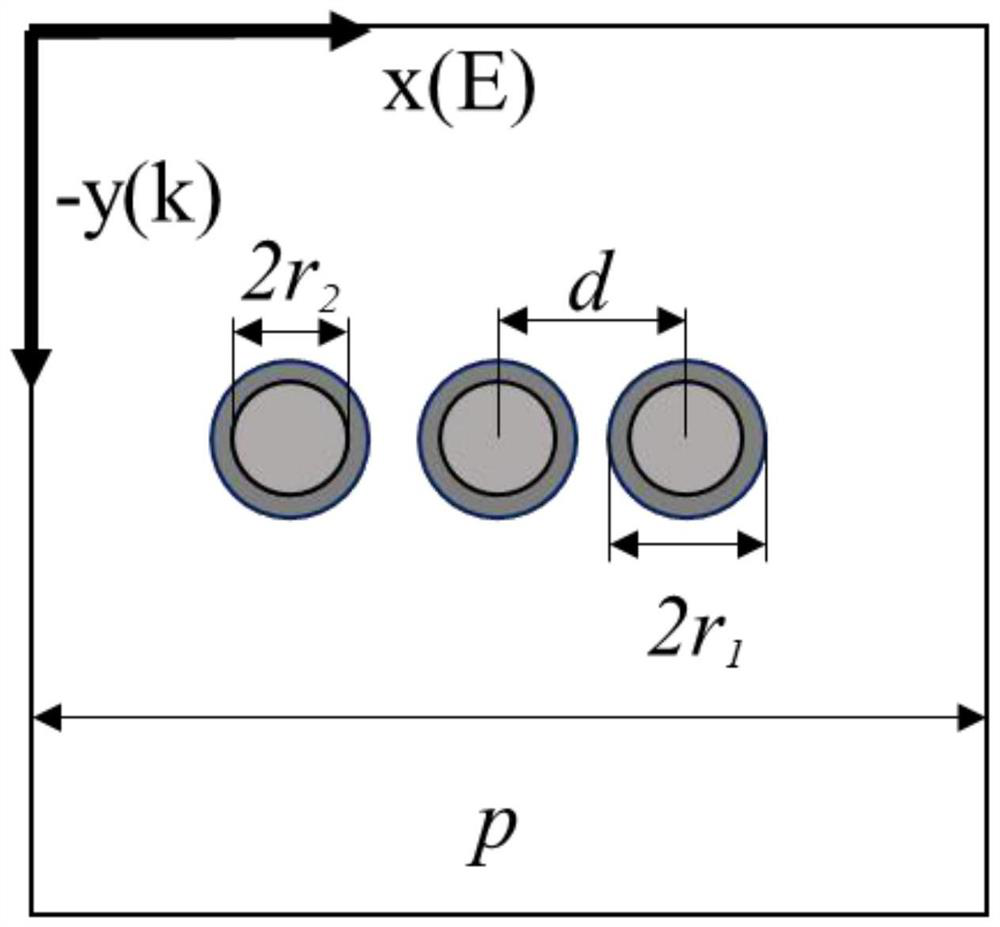
[0023] This embodiment provides a tunable optical switch based on an array of plasmonic columns, such as figure 1 , including: a metasurface with a thickness smaller than the working wavelength, the metasurface has a regular geometric shape, and there are at least three plasmonic columns distributed in parallel and equally spaced within the metasurface;

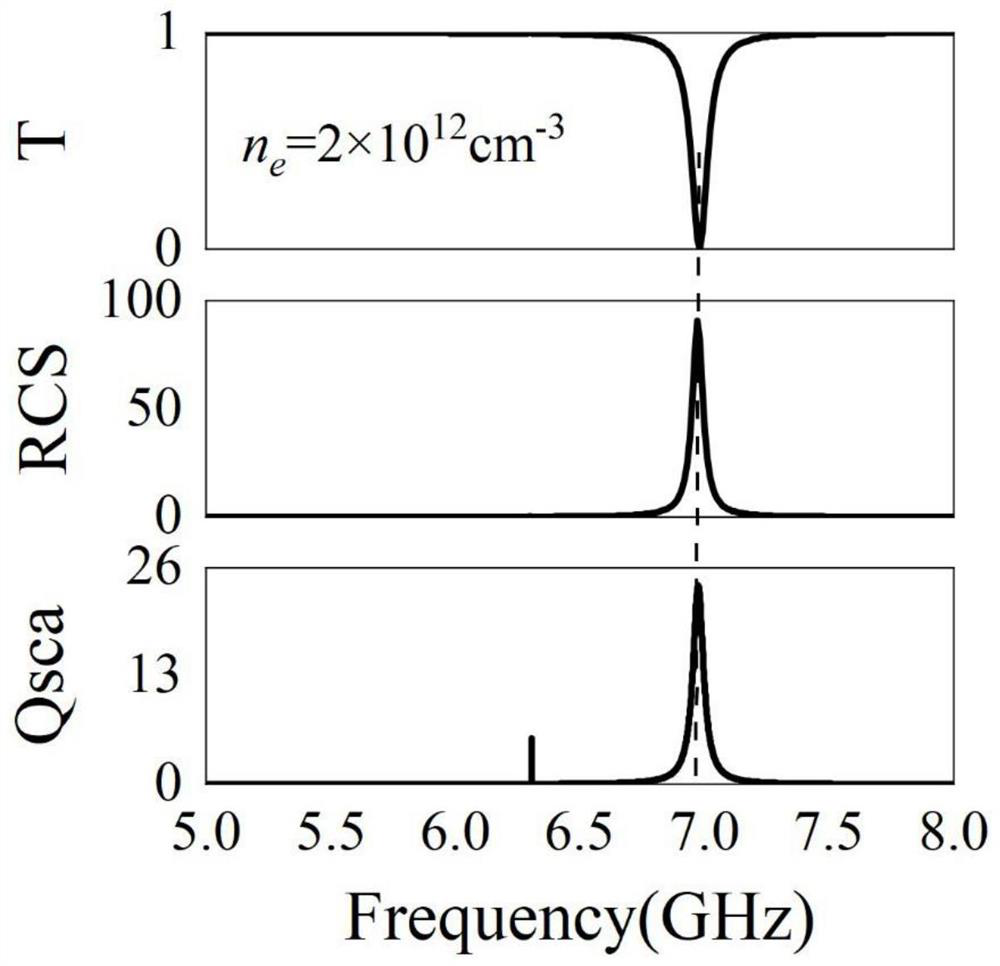
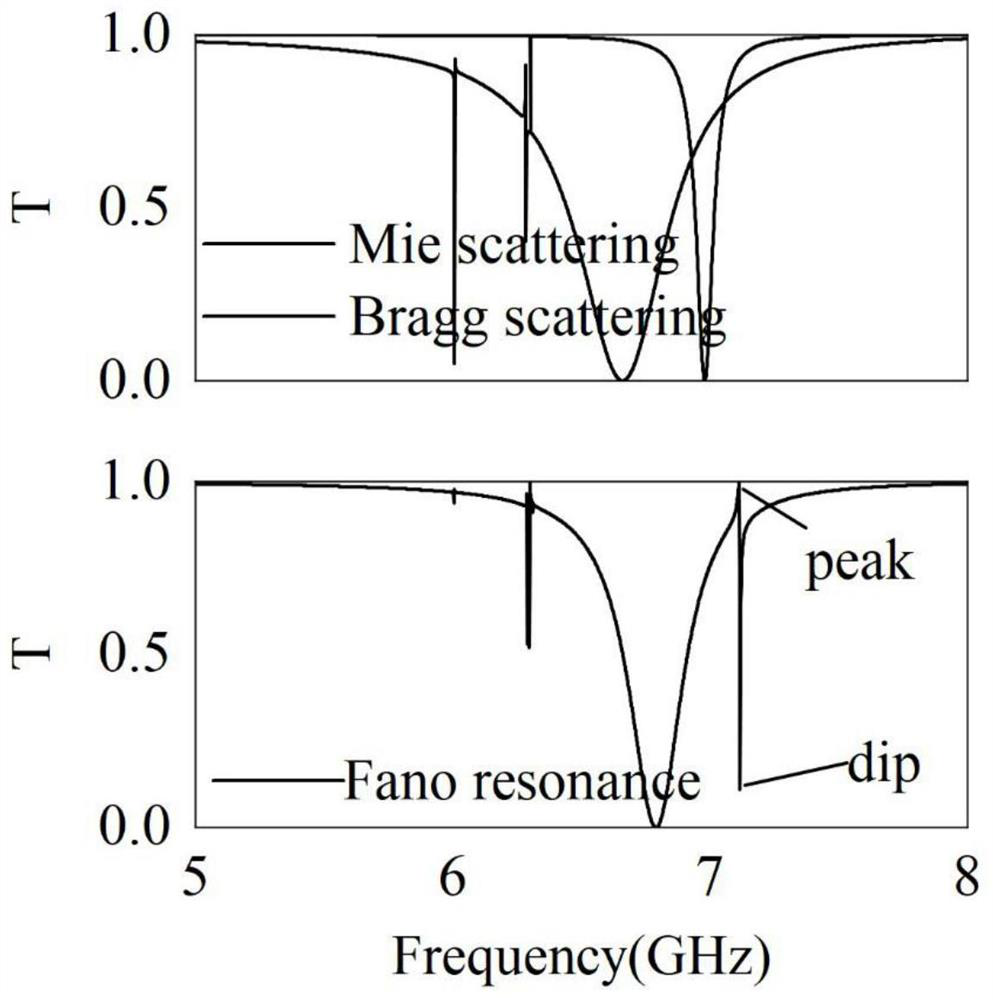
[0024] Using the Mie scattering theory to obtain the Mie scattering coefficient of a single plasma column, so that the Mie scattering of a single plasma column interferes with the Bragg scattering produced by the array plasma column to produce the Fano resonance phenomenon;

[0025] The metasurface is made of clad quartz tubes and plasma columns.

[0026] Specifically, the metasurface is rectangular, and the geometric parameters of all plasmonic columns are exactly the same.

[0027] Specifically, the geometric parameters of the metasurface, the radius of the quartz tube r 1 =1.0mm plasma radius r 1 = 0.66mm metasurface pe...

Embodiment 2

[0041] Present embodiment is on the basis of implementation 1, establishes parameter as d=3.9mm, r 1 =1.0mm, r 2 =0.66mm,n e =2.0×10 12 cm -3 At the same time, use the simulation software based on the finite element method to perform numerical and analytical calculations for the period p, and the results are as follows Figure 5 , is the relationship between transmission coefficient and frequency when the parameter p changes.

[0042] Figure 5 It shows that when 10.0mm<p<12.0mm, the Fano resonance line spectrum has a slight blue shift and the line width narrows; when 12.0mm<p<30.0mm, the Fano resonance frequency remains basically unchanged.

Embodiment 3

[0044] This embodiment is on the basis of embodiment 1, establishes parameter p=18.0mm, r 1 =1.0mm, r 2 =0.66mm,n e =2.0×10 12 cm -3 At the same time, the simulation software based on finite element method is used for numerical and analytical calculation of d, and the results are as follows Figure 6 , is the relationship between transmission coefficient and frequency when the parameters are changed.

[0045] Figure 6 It shows that with the increase of d, the resonance frequency red shifts, but the red shift trend at 2.0mm<d<6.0mm is more obvious than that at 6.0mm<d<8.0mm.

[0046] It can be seen from the above embodiments that the resonant frequency of the Fano resonance can be tuned by changing the geometric parameters, but the tuning frequency range is far less convenient than that obtained by changing the plasma density.


PUM

PropertyMeasurementUnit
Radiusaaaaaaaaaa

Abstract

The invention relates to a tunable optical switch based on array plasma columns. The tunable optical switch based on the array plasma columns solves the technical problems that Fano resonance frequency is uncontrollable and the adjustable degree of freedom is small when Fano resonance is adjusted through geometric parameters, so that the optical switch can realize continuous dynamic adjustabilityof a resonance peak without changing the structural geometric parameters, and a multi-threshold optical switch is realized. The tunable optical switch based on the array plasma columns adopts a technical scheme that the tunable optical switch comprises a super surface with the thickness being less than the working wavelength, the super surface is in a regular geometric shape, and at least three plasma columns are distributed in the super surface in parallel at equal intervals; the plasma columns are made of a cladding quartz tube and filled inert gas; and a Mie scattering coefficient of a single plasma column is obtained by using a Mie scattering theory so as to determine the Mie resonance frequency, then the plasma columns are arrayed to obtain Bragg scattering, and the Mie scattering andthe Bragg scattering are enabled to interfere with each other to generate a Fano resonance phenomenon. The tunable optical switch based on the array plasma columns solves the problems well, and can be applied to the field of optical switches.

Description

technical field [0001] The invention relates to the field of optical switches, in particular to a tunable optical switch based on an array plasma column. Background technique [0002] The Fano resonance is formed by the interference between the wide spectrum of the continuous state and the narrow spectrum of the discrete state to form its asymmetric super-sharp line shape, which is widely used in the fields of sensors, optical switches and biosensing. Electromagnetic waves pass through photonic crystals and are scattered by Bragg to form photonic band gaps, making it possible to manipulate the light path. Plasma photonic crystals are formed by periodic arrangement of plasma to form a photonic crystal structure. Changing the dielectric constant of plasma by changing the density of the plasma can Realize the purpose of changing the photonic bandgap frequency and realize dynamic adjustment. [0003] In the prior art, there are technical problems that the resonance frequency is...

Claims


Application Information

Patent Timeline
IPC IPC(8): G02B5/00
CPCG02B5/008
Inventor 李琦杨天波傅涛安银冰孙堂友肖功利陈永和张法碧刘兴鹏李海鸥
Owner GUILIN UNIV OF ELECTRONIC TECH
Learn More