Supercharge Your Innovation With Domain-Expert AI Agents!

Film formation device

A film-forming device and film-forming chamber technology, which can be used in spraying devices, liquid spraying devices, and devices that apply liquid to surfaces, etc., which can solve the problems of many film-forming situations and difficulty in using large-area substrates, and achieve low cost effect

Active Publication Date: 2020-12-25
TOSHIBA MITSUBISHI-ELECTRIC IND SYST CORP
View PDF8 Cites 0 Cited by
  • Summary
  • Abstract
  • Description
  • Claims
  • Application Information

AI Technical Summary

Problems solved by technology

However, in the chemical vapor deposition method, film formation under vacuum is often required, and a large vacuum vessel is required in addition to a vacuum pump and the like.
Furthermore, in the chemical vapor deposition method, there is a problem that it is difficult to adopt a large-area substrate as a substrate to be filmed from the viewpoint of cost and the like.

Method used


Image

  • Film formation device
  • Film formation device
  • Film formation device

Examples


Embodiment Construction

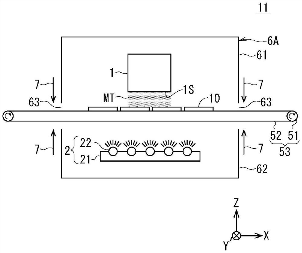
[0030] figure 1 It is an explanatory diagram showing a schematic configuration of a film formation apparatus according to Embodiment 1 of the present invention. exist figure 1 The XYZ orthogonal coordinate system is described in .

[0031] like figure 1 As shown, the film forming apparatus 11 according to Embodiment 1 includes a film forming chamber 6A, a thin film forming nozzle 1 , an infrared light irradiator 2 , and a conveyor 53 as main components.

[0032] The conveyor 53 serving as a substrate loading unit places a plurality of substrates 10 on the upper surface of the belt 52 . The conveyor 53 includes a pair of conveying rollers 51 provided at both left and right (−X direction, +X direction) ends, and an endless conveying belt 52 stretched over the pair of rollers 51 .

[0033] The conveyor 53 can move the belt 52 on the upper side (+Z direction side) along the conveyance direction (X direction) by rotationally driving the pair of rollers 51 .

[0034] The pai...


PUM


Abstract

The purpose of the present invention is to provide a film formation device that makes it possible to form a thin film on a substrate at low cost, without lowering film formation quality or film formation speed. According to the present invention, an infrared radiation apparatus (2) is arranged inside a lower container (62) at a distance from a conveyer (53). The infrared radiation apparatus (2) radiates infrared light upward from a plurality of infrared lamps (22) and thereby executes a heating treatment on a plurality of substrates 10 that have been loaded onto an upper surface of a belt 52.A thin film is formed on the substrates (10) that have been loaded onto the upper surface of the belt (52) as a result of the heating treatment that is executed by means of the infrared light radiatedfrom the infrared radiation apparatus 2 and a mist-spraying treatment that is executed by means of a thin film formation nozzle (1) being executed simultaneously inside a film formation chamber (6A).

Description

technical field [0001] The present invention relates to a film forming apparatus for forming a thin film on a substrate used in the manufacture of electronic devices such as solar cells. Background technique [0002] As a method of forming a film on a substrate, there is a chemical vapor deposition (CVD (Chemical Vapor Deposition)) method. However, in the chemical vapor deposition method, film formation under vacuum is often required, and it is necessary to use a large vacuum vessel in addition to a vacuum pump or the like. Furthermore, in the chemical vapor deposition method, there is a problem that it is difficult to adopt a large-area substrate as a substrate to be filmed from the viewpoint of cost or the like. Therefore, a fog method capable of film formation under atmospheric pressure has attracted attention. [0003] As a prior art related to a film forming apparatus using a mist method, for example, the technology of Patent Document 1 exists. [0004] In the techno...

Claims


Application Information

Patent Timeline
Patent Type & Authority Applications(China)
IPC IPC(8): C23C16/46B05D1/26
CPCB05D1/02B05D1/30B05D3/0263B05D3/0227B05D1/26B05B16/95B05B12/18B05B16/20H05K2203/1105H05K2203/1484H05K2203/1581H05K3/146H05K3/0097H01L21/67115H01L21/6776H01L21/6838H01L21/67103C23C16/46C23C16/4486B05B7/0012B05B7/164
Inventor 织田容征
Owner TOSHIBA MITSUBISHI-ELECTRIC IND SYST CORP
Features
  • R&D
  • Intellectual Property
  • Life Sciences
  • Materials
  • Tech Scout
  • Unparalleled Data Quality
  • Higher Quality Content
  • 60% Fewer Hallucinations
Learn More