
Polishing device used for gear machining and use method of polishing device

A gear and equipment technology, applied in the field of gear processing grinding equipment, can solve the problems of low gear work efficiency, affecting processing quality, and difficulty in rapid grinding and processing of multiple inner circular surfaces of gears, so as to achieve the effect of improving work efficiency.

Inactive Publication Date: 2020-12-29
马鞍山金瓦格机械科技有限公司
View PDF0 Cites 3 Cited by
  • Summary
  • Abstract
  • Description
  • Claims
  • Application Information

AI Technical Summary

Problems solved by technology

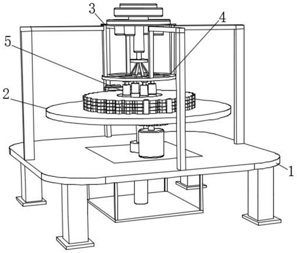
[0004] The purpose of the present invention is to provide a kind of grinding equipment for gear processing and its use method. By setting the frame assembly, positioning assembly, top frame assembly, limit assembly and grinding assembly, the traditional grinding equipment for gear processing is solved. In the process, it is difficult to quickly grind and process the inner circular surfaces of multiple gears at the same time. The efficiency of gear grinding and processing is low, and the gears are prone to deviation during grinding, which affects the processing quality. When the grinding surface of the grinding roller is damaged, it needs to be replaced as a whole. The problem of gear grinding processing cost

Method used


Image

  • Polishing device used for gear machining and use method of polishing device
  • Polishing device used for gear machining and use method of polishing device
  • Polishing device used for gear machining and use method of polishing device

Examples


Embodiment Construction

[0037] The following will clearly and completely describe the technical solutions in the embodiments of the present invention with reference to the accompanying drawings in the embodiments of the present invention. Obviously, the described embodiments are only some, not all, embodiments of the present invention. Based on the embodiments of the present invention, all other embodiments obtained by persons of ordinary skill in the art without creative efforts fall within the protection scope of the present invention.

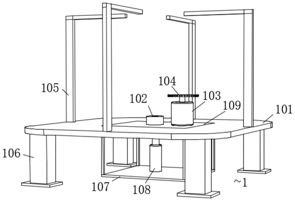
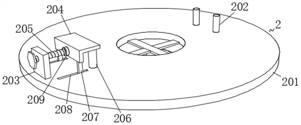
[0038] see Figure 1-9 , the present invention is a grinding equipment for gear processing, comprising a frame assembly 1, a positioning assembly 2 is provided on the inner side of the frame assembly 1, a top frame assembly 3 is provided on the upper end of the frame assembly 1, and a top frame assembly 3 is provided on the top of the top frame assembly. The bottom side of the frame assembly 3 is located directly above the positioning assembly 2, and a limit assemb...


PUM


Abstract

The invention discloses a polishing device used for gear machining and a use method of the polishing device, and relates to the technical field of gear machining. The polishing device comprises a machine frame assembly. A positioning assembly is arranged inside the machine frame assembly. A top frame assembly is arranged at the upper end of the machine frame assembly. A limiting assembly is arranged at the position, over the positioning assembly, of the bottom side of the top frame assembly. Four polishing assemblies are symmetrically arranged on the bottom side of the limiting assembly. The machine frame assembly comprises a fixed base. A fixed bottom frame is fixedly installed at the bottom end of the fixed base, a telescopic cylinder is fixedly installed at the upper end of the fixed bottom frame, and a lifting table is fixedly installed at the telescopic end of the telescopic cylinder. By means of the polishing device and the use method, multiple gears can be conveniently subjectedto polishing machining at the same time, the improvement of the polishing machining work efficiency of the gears is facilitated, the situation that the machining quality is influenced by deviation during gear grinding can be effectively prevented, assembly columns are rotated and subjected to face replacement after being detached and taken out, and polishing faces of polishing rollers can be changed by installing the assembly columns on assembly sliding blocks.

Description

technical field [0001] The invention belongs to the technical field of gear processing, and in particular relates to a grinding device for gear processing and a using method thereof. Background technique [0002] Gears refer to the mechanical elements with gears on the wheel rim that continuously mesh to transmit motion and power. With the development of production, the stability of gear operation has been paid more attention. The tooth shape of the gear includes tooth profile curve, pressure angle, tooth height and displacement. Involute gears are relatively easy to manufacture, so among the gears used in modern times, involute gears account for the absolute majority, while cycloid gears and arc gears are less used. In terms of pressure angle, gears with small pressure angles have a smaller load-carrying capacity; The large pressure angle gear, although the load capacity is high, but the load on the bearing increases under the same transmission torque, so it is only used i...

Claims


Application Information

Patent Timeline
Patent Type & Authority Applications(China)
IPC IPC(8): B23F19/02B23F23/06
CPCB23F19/02B23F23/06
Inventor 周楠
Owner 马鞍山金瓦格机械科技有限公司
Learn More