Multi-wire-harness fiber filament spreading tension control device used in high-pressure hydrogen cylinder production line
A technology of tension control and tension control mechanism, applied in liquid/gas/vapor fiber/sliver/roving processing, transportation and packaging, transportation of filamentous materials, etc., can solve the problem of insufficient dipping, winding interruption, affecting carbon fiber Mechanical properties and other issues, to improve the quality and efficiency of filament winding, reduce the space occupied by equipment, and improve the effect of friction and fluffing.
- Summary
- Abstract
- Description
- Claims
- Application Information
AI Technical Summary
Problems solved by technology
Method used
Image
Examples
Embodiment 1
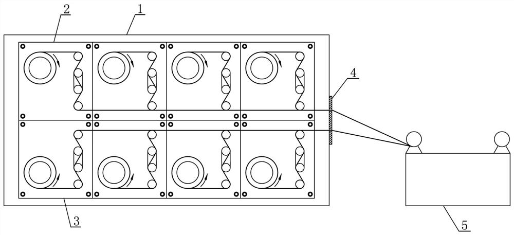
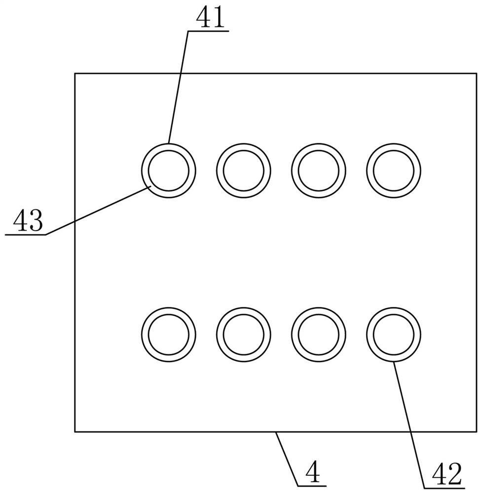
[0031] Such as figure 1 As shown, a multi-bundle fiber spinning tension control device used in a high-pressure hydrogen bottle production line described in this embodiment includes: a wire frame 1, a carbon fiber spinning tension control device and a glass fiber spinning tension control device. The upper and lower positions are installed on the wire frame 1. A dipping tank 5 and a gas cylinder clamping tool are arranged behind the silk rack 1 . The carbon fiber spinning tension control device described in this embodiment is composed of several carbon fiber spinning tension control mechanisms 2, and each carbon fiber spinning tension control mechanism 2 is arranged on the wire frame 1 in a straight line from front to back. The glass fiber spinning tension control device described in this embodiment is composed of several glass fiber spinning tension control mechanisms 3 , and each glass fiber spinning tension control mechanism 3 is arranged on the wire frame 1 in a straight li...
Embodiment 2
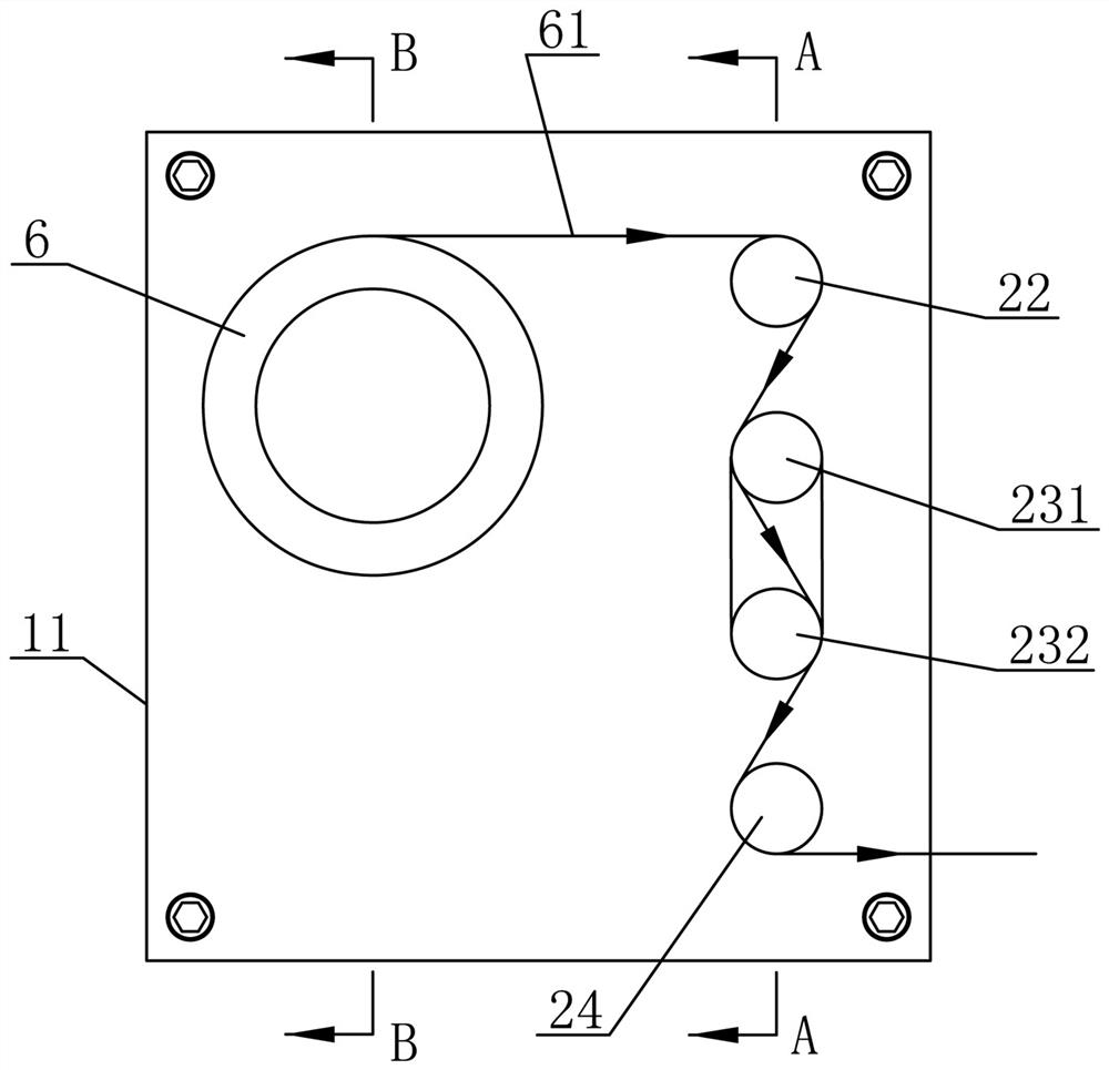
[0037] This embodiment designs the specific structure of the carbon fiber spreading tension control mechanism 2 on the basis of the first embodiment. Such as image 3 , Figure 4 and Figure 5 As shown, the structure of each carbon fiber spreading tension control mechanism 2 includes: a first support roller shaft 21 fixedly sleeved with a first spreading roller 25, a first guide roller shaft 22, a first adjusting roller shaft 23 and a tension belt The first force-measuring roller 24 of the sensor, the first supporting roller 21 , the first guide roller 22 , the first regulating roller 23 and the first force-measuring roller 24 are arranged parallel to each other. One end of the first adjustment roller shaft 23 is a U-shaped adjustment end composed of the first roller shaft 231 and the second roller shaft 232, the other end of the first adjustment roller shaft 23 is the driving end, and the driving end of the first adjustment roller shaft 23 Supported and installed on the in...
Embodiment 3
[0045] This embodiment designs the specific structure of the glass fiber spinning tension control mechanism 3 on the basis of the first or second embodiment. Such as Figure 7 , Figure 8 and Figure 9As shown, the structure of each glass fiber spreading tension control mechanism 3 includes: a second supporting roll 31 fixedly sleeved with a second spreading roll 35, a second guiding roll 32, a second adjusting roll 33 and a belt The second force measuring roller 34 of the tension sensor, the second supporting roller 31 , the second guide roller 32 , the second adjusting roller 33 and the second force measuring roller 34 are arranged parallel to each other. One end of the second adjustment roller shaft 33 is a U-shaped adjustment end formed by the third roller shaft 331 and the fourth roller shaft 332, the other end of the second adjustment roller shaft 33 is the driving end, and the driving end of the second adjustment roller shaft 33 It is installed on the installation pa...
PUM
 Abstract
Description
Claims
Application Information
 - R&D
- Intellectual Property
- Life Sciences
- Materials
- Tech Scout
- Unparalleled Data Quality
- Higher Quality Content
- 60% Fewer Hallucinations
Browse by: Latest US Patents, China's latest patents, Technical Efficacy Thesaurus, Application Domain, Technology Topic, Popular Technical Reports.
© 2025 PatSnap. All rights reserved.Legal|Privacy policy|Modern Slavery Act Transparency Statement|Sitemap|About US| Contact US: help@patsnap.com


