
Electric power material loading and unloading device

A technology for loading and unloading devices and power materials, which is applied in transportation and packaging, load hanging components, springs/shock absorbers, etc. The effect of transportation and smooth handling

Pending Publication Date: 2020-12-29
YANTAI POWER SUPPLY COMPANY OF STATE GRID SHANDONG ELECTRIC POWER
View PDF6 Cites 3 Cited by
  • Summary
  • Abstract
  • Description
  • Claims
  • Application Information

AI Technical Summary

Problems solved by technology

[0002] Power equipment mainly includes power generation equipment and power supply equipment. Power generation equipment is mainly power plant boilers, steam turbines, gas turbines, water turbines, generators, transformers, etc. Power supply equipment is mainly transmission lines of various voltage levels, transformers, contactors, etc. Power supplies are used in their daily maintenance and overhaul. Power supplies refer to the collective name of all equipment in the process of using electricity. At present, when erecting or overhauling power facilities, due to the volume It is relatively large and heavy, and it is very inconvenient to carry. It needs to use some machinery to carry it. However, there are some problems in the current power material loading and unloading device: 1. When the loading device loads its power material, because of Excessive weight of electrical equipment may cause its device to be unstable when hoisting it, and the uneven road surface will cause the electrical equipment to shake during transportation, making it fall down and causing danger to workers; 2. When fixing the equipment, the traditional hoisting devices are all hook-type, and you need to prepare the hoisting rope by yourself. When fixing it, it is easy to cause the center of gravity to shift, and it is extremely troublesome to bind the power materials and equipment, which affects work efficiency. Therefore, It is necessary to design a power material handling device

Method used


Image

  • Electric power material loading and unloading device
  • Electric power material loading and unloading device
  • Electric power material loading and unloading device

Examples


Embodiment

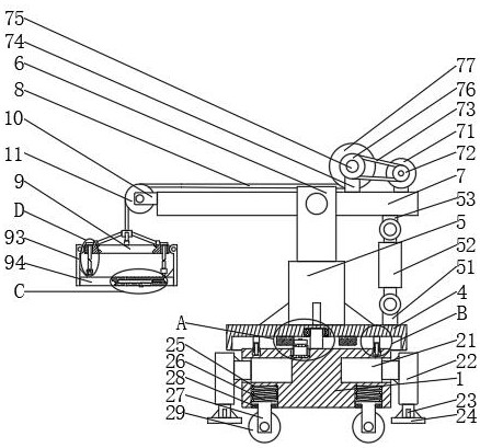
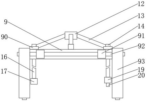
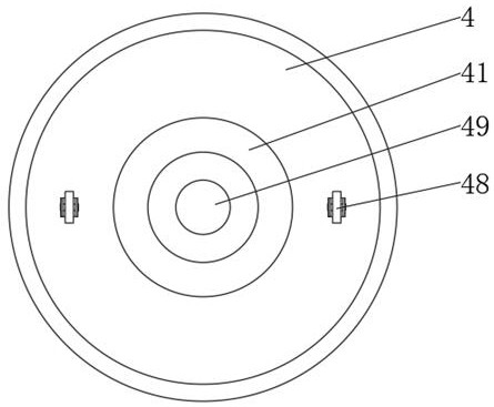
[0027] A power material loading and unloading device, comprising a base 1, a fixed shaft 2, a bearing 3, a turntable 4, a cylinder barrel 5, a cylinder rod 6, a hoisting rod 7, a steel rope 8, a hoisting plate 9 and a bracket 1 10, characterized in that: The upper end of the base 1 is fixedly connected with a fixed shaft 2, the upper end of the fixed shaft 2 is rotatably connected with a bearing 3, the outer side of the bearing 3 is fixedly connected with a turntable 4, and the upper end of the turntable 4 is welded with a cylinder barrel 5, so The inside of the cylinder barrel 5 is slidably connected with a cylinder rod 6, the upper end of the cylinder rod 6 is hinged with a hoisting rod 7, the left end of the hoisting rod 7 is fixedly connected with a bracket one 10, and the left end of the bracket one 10 is rotatably connected with a Pulley 11, the outer side of the pulley 11 is slidably connected with the steel rope 8, the lower end of the steel rope 8 is fixedly connected ...


PUM


Abstract

The invention discloses an electric power material loading and unloading device. The electric power material loading and unloading device comprises a base, a stationary shaft, a bearing, a rotating disc, a cylinder barrel, a cylinder rod, a hoisting rod, a steel rope, a hoisting plate and a bracket I, wherein the stationary shaft is fixedly connected to the upper end of the base; the bearing is rotationally connected to the upper end of the stationary shaft; the rotating disc is fixedly connected to the outer side of the bearing; the cylinder barrel is welded to the upper end of the rotating disc; the cylinder rod is slidably connected to the interior of the cylinder barrel; the hoisting rod is hinged to the upper end of the cylinder rod; the bracket I is fixedly connected to the left endof the hoisting rod; a pulley is rotationally connected to the left end of the bracket I; the steel rope is slidably connected to the outer side of the pulley; a connecting block is fixedly connectedto the lower end of the steel rope; and adjusting ropes are fixedly connected to the outer side of the connecting block. The electric power material loading and unloading device provided by the invention has the characteristics of being capable of stably hoisting and transporting electric power materials and being quickly bound and fixed.

Description

technical field [0001] The invention belongs to the technical field of electric power material transportation, in particular to a power material loading and unloading device. Background technique [0002] Power equipment mainly includes two categories: power generation equipment and power supply equipment. Power generation equipment is mainly power station boilers, steam turbines, gas turbines, hydraulic turbines, generators, transformers, etc. They will use power materials in their daily maintenance and repairs. Power materials refer to the collective name of all equipment in the process of using electricity. At present, when erecting power facilities or overhauling power facilities, due to the volume of power equipment and materials It is relatively large and heavy, and it is very inconvenient to carry. Some machinery is needed to carry it. However, there are some problems with the current power material loading and unloading device: 1. When the loading device loads its po...

Claims


Application Information

Patent Timeline
IPC IPC(8): B66C23/16B66C23/62B66C23/80B66C23/84B66C1/16B66C1/12B66C1/44F16F15/067
CPCB66C23/16B66C23/62B66C23/80B66C23/84B66C1/16B66C1/12B66C1/44F16F15/067
Inventor 张一荻孙盛毅贺丽丽郭范宁史晓明刘伟宋歌郎元彬
Owner YANTAI POWER SUPPLY COMPANY OF STATE GRID SHANDONG ELECTRIC POWER
Learn More