Inner column type umbrella-shaped expanding equipment and expanding method thereof

An umbrella-shaped and column-shaped technology, which is applied in construction, sheet pile walls, foundation structure engineering, etc., can solve problems such as loose movement, poor machining performance of easy-cutting materials, and recyclable anchor reinforcement fixing limit devices, etc.

Pending Publication Date: 2020-12-29
刘晓理
View PDF0 Cites 10 Cited by
  • Summary
  • Abstract
  • Description
  • Claims
  • Application Information

AI Technical Summary

Problems solved by technology

However, in the umbrella cage structure where the drilling space is limited and the cross-sectional area is limited, such a distribution pattern makes the cross-sectional area cost-effectiveness ratio (that is, the proportion of cross-sectional area / pressure-bearing performance) of the structural members larger, and the cross-sectional area cost-effectiveness ratio is relatively large. The form with the smallest ratio and the most space-saving is to set the structural components at the central axis of the lacing plate and the penetrating plate, but the problem is that the structural components can only be set outside the central bolt, so it is impossible to Realize the locking and recruitment of the central bolt method of the pre-retractable umbrella cage, and the locking and recruitment of the central bolt method is the most convenient, economical and effective method among all the locking and recruitment methods of the umbrella-shaped expansion device at present, and the pre-retractable umbrella cage It is the general trend of the development of the industry, which is a pair of contradictions that exist objectively
[0006] In addition, there are many problems in the fixing of the limit device on the structural member or the anchor bar. For example, the traditional bonded anchor bar is about to be eliminated, and the recyclable anchor bar (in other words, no bonded anchor bar) It is impossible to fix the limit device on the anchor bar at all; while fixing the limit device with threads on the free-cutting anchor (represented by basalt fiber anchor) often loosens and moves during the anchoring construction process. And it is forbidden to fix with pins; the fixing of the limit device on the structural member is usually fixed by thread, pin or electric welding. Among them, the welding fixation is difficult to standardize and cannot be adjusted once welding is applied, and the screw fixing is prone to loosening and running. If the pin shaft is fixed, the strength of the structural member will be affected by the drilling and perforation, etc.
[0007] In addition, due to the poor machinability of easy-cutting materials and the unsatisfactory overall shear resistance and local shear resistance of joints participating in the steel component system, when no easy-cutting materials are used for anchor bars and structural components, structural components As the longest and largest component left in the ground except for the anchor bars, it has a greater risk of damaging the shield machine tunneling system and clogging the muck conveying system, which is not in line with the industry development trend and the pace of the times using recyclable anchor bars. Adaptation is not conducive to the environmental friendliness of the umbrella-shaped expansion head technology, and constitutes an obstacle to the popularization and application of the umbrella-shaped expansion head technology

Method used


Image

  • Inner column type umbrella-shaped expanding equipment and expanding method thereof
  • Inner column type umbrella-shaped expanding equipment and expanding method thereof
  • Inner column type umbrella-shaped expanding equipment and expanding method thereof

Examples


Embodiment 1

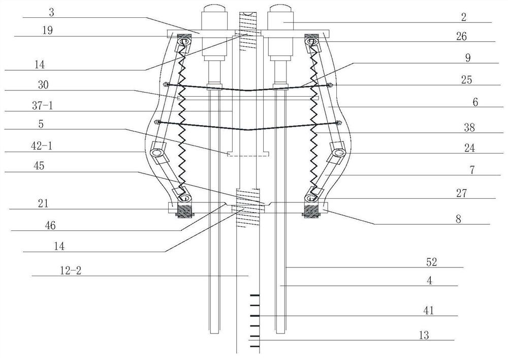
[0096]The inner-column umbrella-shaped expansion device includes several anchor bars 4, several load conversion devices 2, and several umbrella-shaped expansion devices. Each umbrella-shaped expansion device includes at least one umbrella-shaped folding rod group. The umbrella-shaped folding The rod group is folded forward or reversely, and each umbrella-shaped folding rod group includes several folding rods, and at the front and rear ends of the umbrella-shaped folding rod group, the folding rods are centrally hinged and restrained in a centrally symmetrical shape; The load conversion device 2 is fixedly or unidirectionally connected to the umbrella-shaped expansion device, the anchor bars 4 are fixed or detachable fixed or movably penetrated on the load conversion device 2, and the load conversion device and the umbrella-shaped expansion device are fixed or single. It also includes the tensioning plate 3 and / or the threading plate 8, and also includes several longitudinally d...

Embodiment 2

[0194] Embodiment 2: as figure 1 As shown, the umbrella-shaped expansion device is implanted in the pre-retracted state; the anchor bar is Suzhou Nenggong's recyclable anchor cable, and the tension plate of the umbrella-shaped expansion device is directly used as the anchor plate, the hole is pre-expanded, and the umbrella is fixed by the screw bolt method. The pre-shrinkage locking and unlocking of the umbrella-shaped expansion device and the recovery; the pressure-bearing column I and the receiving pit are set up, and the perfusion tube is also used as a measuring tool to implement the recruitment discrimination of the umbrella-shaped expansion device. The perfusion tube can be retracted for reuse and passed Measures to realize the non-through-body setting of the thread.

Embodiment 3

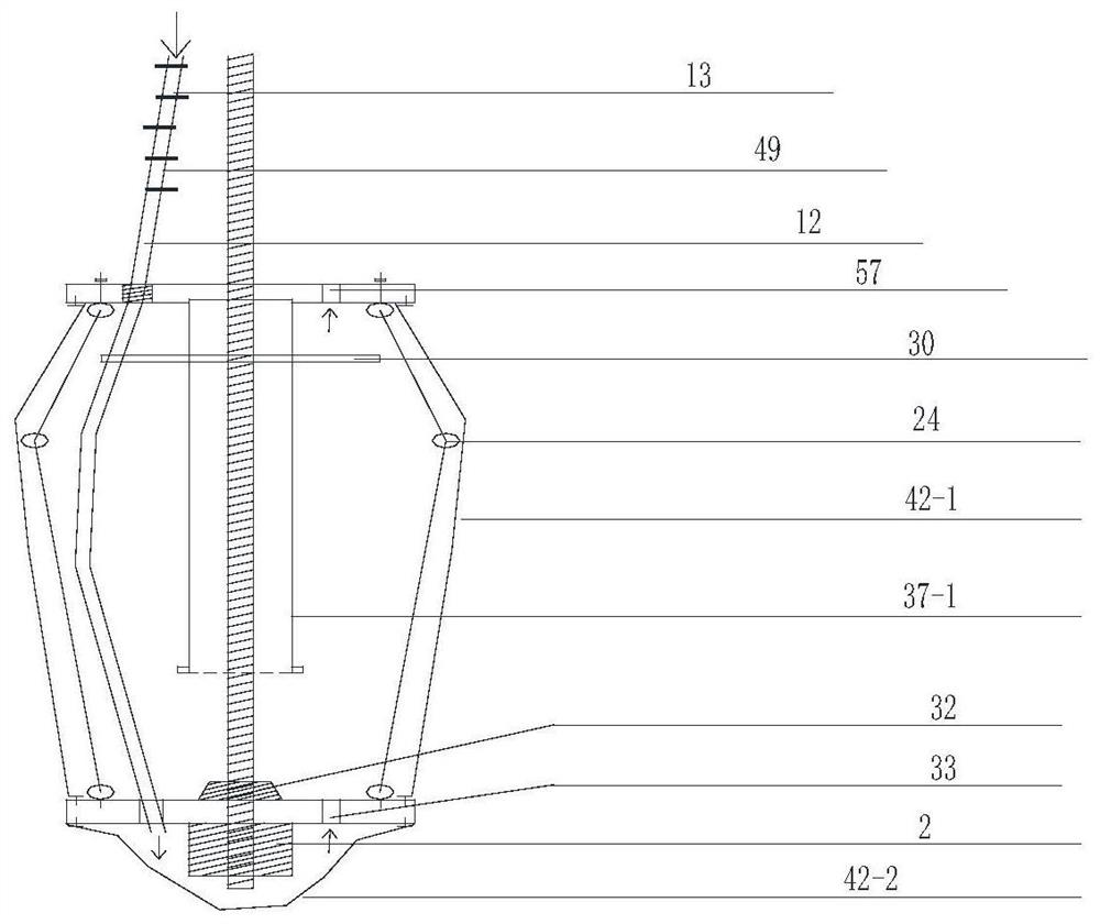
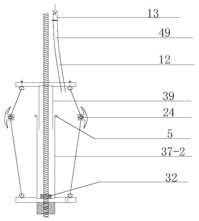
[0196] like figure 2 As shown, the downward-sloping hole, the umbrella-shaped expansion device is implanted in the pre-retracted state; there is a single pressure-bearing column I, the front end of the pressure-bearing column I is a non-fixed end, the rear end is fixed on the rib plate, and the anti-sag device is fixed On the pressure-bearing column Ⅰ, set a pushing device on the anchor bar at the rear side of the lacing pan; the middle part of the perfusion pipe passes through the lacing plate and is fixed on the tying plate, and the front end passes through the lacing plate and is fixed on the lacing plate On the top, the perfusion tube is also used as a measuring tool and a pull rope; a membrane bag is set to separate the anchor head and the umbrella-shaped expansion device from the external environment; At the rear end of the anchor bar, use the anchor bar to push the umbrella-shaped expansion device into the reaming section, then loosen the perfusion tube, the bar pierci...


PUM


Abstract

The invention discloses inner column type umbrella-shaped expanding equipment and an expanding method thereof. The inner column type umbrella-shaped expanding equipment comprises an umbrella-shaped expanding device and a plurality of longitudinally-distributed inner columns; and the inner columns are pressure-bearing columns I or telescopic pressure-bearing columns or telescopic pull rods; when the number of the inner column is one, the inner column is located on the central axis of the umbrella-shaped folding rod set; when the number of the inner columns is larger than or equal to two, the multiple inner columns are distributed around the central axis of the umbrella-shaped expanding body device; the inner columns are combined or independently arranged; the combined arrangement of the inner columns comprises combined arrangement of a tie bar disc and the front end of the inner column and/or combined arrangement of a tie bar penetrating disc and the rear end of the inner column; when the inner columns are the pressure-bearing columns I, one ends of the pressure-bearing columns I are hinged to the front ends or the rear ends of all the folding rods, and the other ends of the pressure-bearing columns I are located between the front end and the rear end of the umbrella-shaped folding rod set; and when the inner columns are the telescopic pressure-bearing columns or the telescopicpull rods, the two ends of the telescopic pressure-bearing columns or the telescopic pull rods are fixedly connected with the front end and the rear end of the umbrella-shaped folding rod set respectively. The inner column type umbrella-shaped expanding equipment and the expanding method thereof are used for achieving the purpose of optimizing the pre-collection type three-hinge pressure-bearing structure.

Description

technical field [0001] The invention relates to the field of geotechnical engineering, in particular to an inner-column umbrella-shaped expansion device and an expansion method thereof. Background technique [0002] The umbrella-shaped expansion head involves the field of geotechnical engineering, and is specifically used in temporary foundation pit support, permanent slope support, water conservancy and hydropower, civil air defense, underground engineering, national defense, etc. Anti-floating bolt anchor cable, tunnel vault support, etc. [0003] In the existing umbrella-shaped expansion head series technology, the realization of the ultra-high pull-out force of the umbrella-shaped expansion head is realized by a three-hinge bearing structure constructed with structural members, long rods, and short rods; It needs to move through the lacing plate or the piercing plate. When the umbrella cage expands, the lacing plate needs to slide from the front end or the rear end to t...

Claims


Application Information

Patent Timeline
Patent Type & Authority Applications(China)
IPC IPC(8): E02D5/76
CPCE02D5/76
Inventor 刘晓理
Owner 刘晓理
Why Eureka
Try Eureka