Engine exhaust pressure electronic waveform detection and identification method and system
An exhaust pressure and waveform detection technology, applied in engine testing, engine components, combustion engines, etc., can solve the problems of extensive detection and maintenance, lack of generator exhaust electronic pressure waveform detection and analysis, etc., to achieve a broad market application space , improve the technical level, enrich the effect of technical means
- Summary
- Abstract
- Description
- Claims
- Application Information
AI Technical Summary
Problems solved by technology
Method used
Image
Examples
Embodiment 1
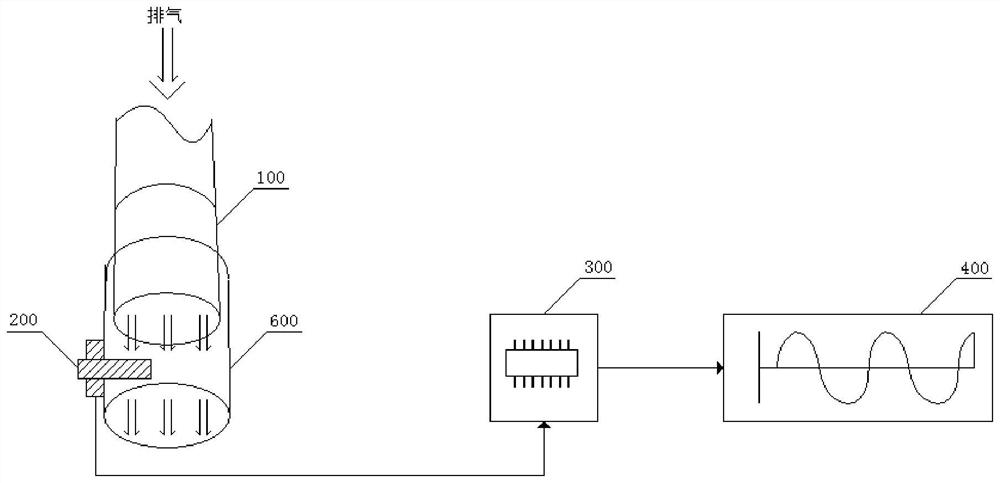
[0033] The electronic waveform detection method of the engine exhaust pressure includes: refer to figure 1 ,
[0034] ① Install an exhaust pressure sensor 200, place the exhaust pressure sensor 200 through the sleeve 600 on the exhaust pipe of the vehicle to be detected, so that the sensor is located within 2cm of the outlet of the exhaust pipe 100, and place the exhaust pressure sensor 200 The susceptible surface faces the direction of the exhaust source;
[0035] ② Detect and record the electronic waveform of the output signal of the exhaust pressure sensor;
[0036] ③Respectively adjust the working conditions of the engine so that the engine is in one or more of the idling conditions, light load conditions, medium compliance conditions, heavy load conditions, and acceleration conditions, and record the corresponding exhaust conditions. Electronic waveform of a barometric pressure sensor.
[0037] Identification methods include:
[0038]①Frequency domain identification: ...
Embodiment 2
[0051] Such as figure 1 As shown, the system includes an exhaust pressure sensor 200, a data processing unit 300 and a display unit 400. The exhaust pressure sensor 200 is placed at the exhaust pipe port of the vehicle to be detected through the sleeve 600, so that the sensor is located at the exhaust pipe 100 Within the range of 2cm from the outlet, there is also an exhaust pressure sensor connected to a data processing unit, which is used to transmit the electronic signal output by the exhaust pressure sensor to the data processing unit, and the data processing unit detects the electronic waveform of the engine exhaust pressure according to Embodiment 1. and identification method for calculation processing; the data processing unit is also connected to the display unit for terminal display of the calculation results through the display unit. It is output first, and the displayed information is used to analyze the operating characteristics of the engine, the performance of th...
Embodiment 3
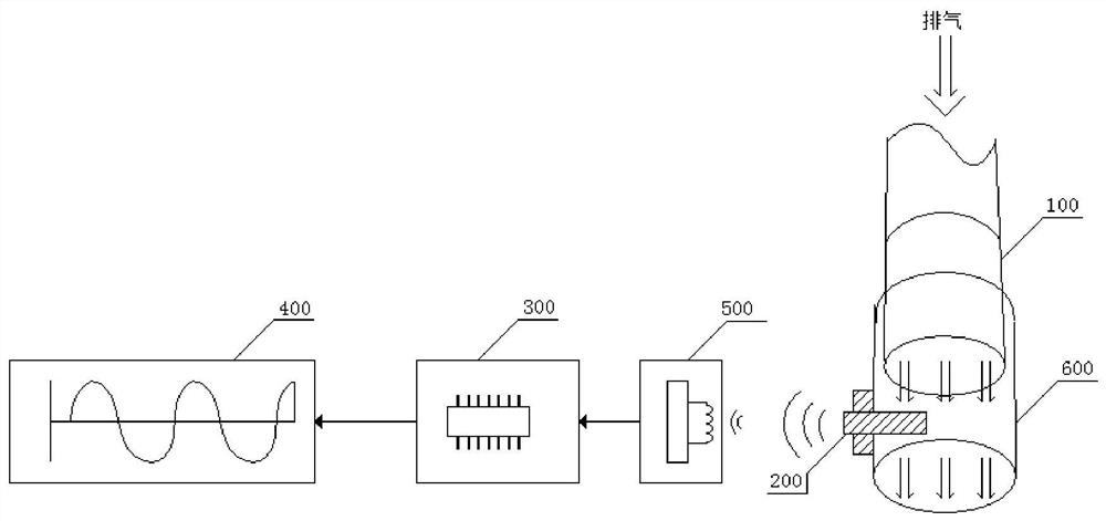
[0055] Such as figure 2 As shown, the system includes an exhaust pressure sensor 200, a wireless data receiving unit 500, a data processing unit 300 and a display unit 400. The exhaust pressure sensor 200 is placed at the exhaust pipe port of the vehicle to be detected through the sleeve 600, so that The sensor is located within 2cm of the outlet of the exhaust pipe 100. The exhaust pressure sensor can be provided with a signal transmitting device, and the radio frequency signal is transmitted and output by wireless transmission. The wireless data receiving unit receives the radio frequency signal transmitted and output by wireless transmission, and the wireless data is received. The unit is connected to the data processing unit, which is used to receive the radio frequency electronic signal output by the exhaust pressure sensor and then transmit it to the data processing unit. The data processing unit performs calculation processing according to the electronic waveform detect...
PUM
 Abstract
Description
Claims
Application Information
 - R&D
- Intellectual Property
- Life Sciences
- Materials
- Tech Scout
- Unparalleled Data Quality
- Higher Quality Content
- 60% Fewer Hallucinations
Browse by: Latest US Patents, China's latest patents, Technical Efficacy Thesaurus, Application Domain, Technology Topic, Popular Technical Reports.
© 2025 PatSnap. All rights reserved.Legal|Privacy policy|Modern Slavery Act Transparency Statement|Sitemap|About US| Contact US: help@patsnap.com


