Design method of a closed-loop current sensor

A technology of current sensor and design method, which is applied in the field of sensors, can solve problems such as circuit complexity and cost increase, and achieve the effects of reducing power consumption, solving magnetic flux leakage problems, and reducing costs

Active Publication Date: 2021-07-13
珠海多创科技有限公司
View PDF10 Cites 0 Cited by
  • Summary
  • Abstract
  • Description
  • Claims
  • Application Information

AI Technical Summary

Problems solved by technology

Moreover, the circuit of the closed-loop current sensor is more complicated due to the addition of a feedback system, which will also increase the cost.

Method used


Image

  • Design method of a closed-loop current sensor
  • Design method of a closed-loop current sensor
  • Design method of a closed-loop current sensor

Examples


Embodiment 1

[0047] Design a closed-loop current sensor with 100A ~ 4V output, accuracy requirement: 0.5%, power consumption requirement: 1W.

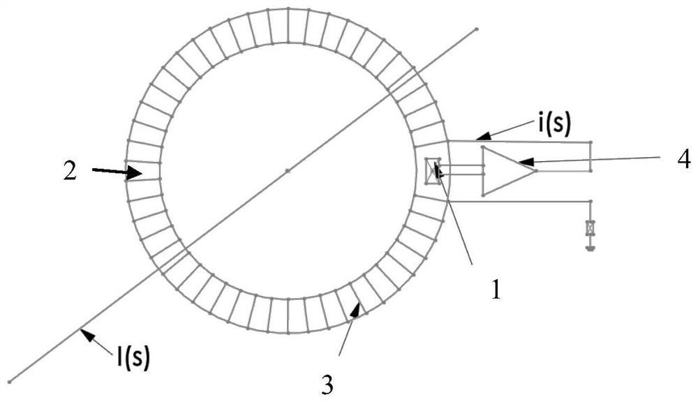
[0048] First, determine the sensor structure according to the use requirements of the sensor. The sensor adopts a skeleton shell of 35×27×4. The total number of turns of the coil is determined according to the size of the skeleton shell and the measured current. Since the outer diameter of the sensor is required to be 25mm, the The total number of turns of the coil is designed to be 1000 turns; this embodiment adopts an all-hollow magnetic circuit, that is, no iron core is arranged in the skeleton shell, and the function of the skeleton shell is to wind the feedback coil and fix the magnetic sensing chip ( Figure 4 ), the magnetic sensing chip adopts the tunnel magnetoresistance chip;

[0049] Determine the size of the secondary current according to the power consumption of the sensor. The power consumption requirement of the sensor is 1W, and the...

Embodiment 2

[0054] Design a closed-loop current sensor with 100A ~ 4V output, accuracy requirement: 0.5%, power consumption requirement: 1W.

[0055] First, determine the sensor structure according to the use requirements of the sensor. The sensor adopts a skeleton shell of 35×27×4. The total number of turns of the coil is determined according to the size of the skeleton shell and the measured current. Since the outer diameter of the sensor is required to be 25mm, the The total number of turns of the coil is designed to be 1000 turns; the iron core of this embodiment is composed of 12 iron core segments arranged at even intervals along the circumference ( Figure 5 ), the 12-section iron core segment and the magnetic sensing chip are arranged in the skeleton shell ( Figure 6 ), the magnetic sensing chip adopts the tunnel magnetoresistance chip;

[0056] Determine the size of the secondary current according to the power consumption of the sensor. The power consumption requirement of the ...


PUM


Abstract

A design method of a closed-loop current sensor, the closed-loop current sensor includes a magnetically sensitive chip, a magnetic circuit, a feedback coil and a signal processing circuit, the magnetic circuit consists of iron core segments arranged at intervals along the circumferential direction or is a full hollow magnetic circuit, The design method of the current sensor includes the following steps: determine the structure of the sensor; determine the size of the secondary current; determine the standard feedback amount of the sensor according to the secondary current and the number of coil turns, and then determine the design feedback amount of the sensor; calculate the conversion of the current to the magnetic field The value of the function; calculate the magnification K of the signal processing circuit, and determine the signal processing circuit after determining the magnification of the signal processing circuit, thereby completing the overall design of the closed-loop current sensor. The invention can effectively reduce the power consumption of the sensor, reduce the cost, balance the problems of accuracy and power consumption encountered in the current sensor, and is especially suitable for the design of a closed-loop current sensor with high precision, large range and low power consumption.

Description

technical field [0001] The invention belongs to the technical field of sensors, and in particular relates to a design method of a magnetoresistance-based closed-loop current sensor. Background technique [0002] In recent years, the wave of smart grid has swept the world, and it has become a major research topic for global energy development and transformation in the current low-carbon and high-efficiency economy era. In order to realize the real-time monitoring and control of the smart grid, advanced sensing and measurement technologies need to be developed urgently. The core of the smart grid is the deep integration of power energy flow and information flow, which is based on the deep perception and control of the grid situation based on information technology. The smart grid can monitor the real-time information of each key node and equipment, realize the real-time optimization and scheduling of the power grid through advanced control decision-making technology, improve ...

Claims


Application Information

Patent Timeline
Patent Type & Authority Patents(China)
IPC IPC(8): G01R19/00
CPCG01R19/0092
Inventor 朱家训范群国刘明陈荣郑若麟白咪
Owner 珠海多创科技有限公司
Why Eureka
Try Eureka