
Fog gun machine for construction site and using method

A construction site, fog cannon technology, applied in cleaning methods and appliances, chemical instruments and methods, ion exchange column/bed methods, etc., can solve problems such as circuit component erosion, unfavorable operation and treatment, and no good dust-proof mechanism. Achieve the effect of adjusting the spraying distance and facilitating operation and handling

Active Publication Date: 2021-01-01
ZHONGQI JIAOJIAN GRP
View PDF5 Cites 2 Cited by
  • Summary
  • Abstract
  • Description
  • Claims
  • Application Information

AI Technical Summary

Problems solved by technology

[0005] Aiming at the deficiencies of the prior art, the present invention provides a fog cannon for construction sites and its use method, which solves the problem that the angle of the fog blowing pipe cannot be changed without a good angle adjustment mechanism inside the fog blowing pipe. Changing the spraying distance and coverage area of ​​the spray tube is not conducive to the operation and treatment of it by external personnel, and at the same time it cannot effectively complete the dust suppression work on the dust. At the same time, there is no good dust-proof mechanism outside the device, which leads to frequent erosion of external dust to the inside of the frame, causing the internal circuit components of the frame to be corroded by external dust, shortening the service life

Method used


Image

  • Fog gun machine for construction site and using method
  • Fog gun machine for construction site and using method
  • Fog gun machine for construction site and using method

Examples


Embodiment Construction

[0035] The following will clearly and completely describe the technical solutions in the embodiments of the present invention with reference to the accompanying drawings in the embodiments of the present invention. Obviously, the described embodiments are only some, not all, embodiments of the present invention. Based on the embodiments of the present invention, all other embodiments obtained by persons of ordinary skill in the art without making creative efforts belong to the protection scope of the present invention.

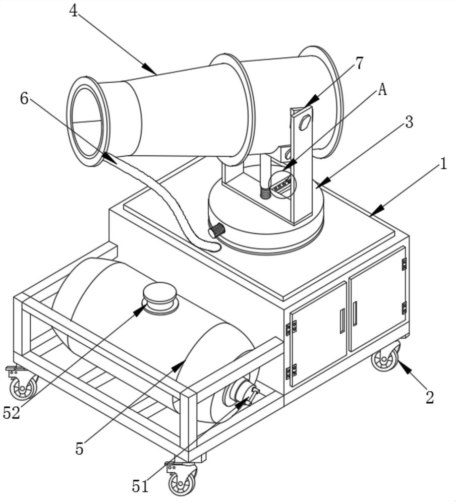
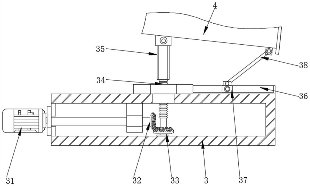
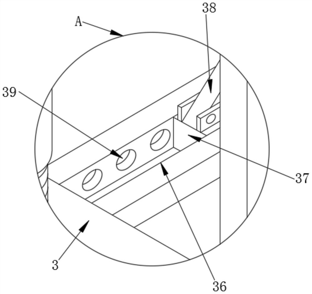
[0036] see Figure 1-4 , the present invention provides a technical solution: a fog cannon machine for a construction site and its use method, comprising a frame body 1, movable wheels 2 are fixedly installed at the four peripheral corners of the lower end surface of the frame body 1, and the middle of the upper end surface of the frame body 1 The position is rotatably connected with a rotating disc 3, and the upper end surface of the rotating disc 3 is rotata...


PUM


Abstract

The invention discloses a fog gun machine for a construction site and a using method, and relates to the technical field of fog gun machines. The fog gun machine comprises a frame body, movable wheelsare fixed to the corners of the periphery of the lower end face of the frame body, and a rotating disc is rotationally arranged in the middle of the upper end face of the frame body; the upper end face of the rotating disc is rotationally connected with a mist blowing pipe through a clamping concave rod, a water tank is fixed to one side of the interior of the frame body, a servo motor is fixedlyinstalled on one side of the annular outer surface of the rotating disc, and a telescopic connecting hose is fixedly connected between the mist blowing pipe and the frame body. A second rotating gearis fixedly mounted at the output end of the servo motor. According to the fog gun machine, the spraying angle can be effectively changed, so that the spraying distance of spraying is effectively adjusted, external personnel can conveniently perform operation treatment, external dust can be prevented from entering the frame body, and the situation that the service life of circuit elements is shortened due to the fact that the external dust erodes the interiors of the circuit elements of the frame body is avoided.

Description

technical field [0001] The invention relates to the technical field of fog cannons, in particular to a fog cannon for construction sites and a method of use. Background technique [0002] The construction site will generate a lot of dust during the construction process, and a large number of construction sites are located near residential areas, and the dust on the ground will enter the atmosphere due to wind, human-driven and other open sources of pollution, which will form An important part of the total suspended particulate matter in the ambient air, which affects the environment and has a serious impact on the surroundings; long-term exposure to this environment is also harmful to the human body, causing a large number of diseases, such as bronchitis, lung cancer, and seriously affecting normal life; this It is necessary to condense the dust in the air through the fog cannon before landing. [0003] Patent Publication No. CN109731423A discloses an environment-friendly f...

Claims


Application Information

Patent Timeline
IPC IPC(8): B01J47/06B08B9/087
CPCB01J47/06B08B9/087
Inventor 柳德水马锡腾贾鹏
Owner ZHONGQI JIAOJIAN GRP
Learn More