Wind power generation device and mounting method thereof

A technology of a wind power generation device and an installation method, which is applied to wind power generation, wind turbines, motors, etc., can solve the problems of increasing low-voltage line current, increasing cost, and increasing the proportion of line cost, so as to reduce vibration amplitude and vibration time. Effect

Pending Publication Date: 2021-01-01
MECAL(北京)工程技术有限公司
View PDF0 Cites 2 Cited by
  • Summary
  • Abstract
  • Description
  • Claims
  • Application Information

AI Technical Summary

Problems solved by technology

[0004] With the development of wind power generation technology, the power generation capacity of a single machine is increasing. Due to the increase of the capacity of a single machine, the mode of power generation and transformation will inevitably change. The early wind power transformers are generally placed on the ground, and the distance between the engine room and the transformer The line is a low-voltage line, but as the capacity of a single machine continues to increase, the current of the low-voltage line also continues to increase, resulting in an increase in the cost of the line
Therefore, the current large-capacity wind turbines place the transformer on the tower, so that the transmission cables in the tower are high-voltage cables, and the requirements for the cable section are reduced. After reaching a certain capacity, high-voltage line transmission is more economical than low-voltage transmission

Method used


Image

  • Wind power generation device and mounting method thereof
  • Wind power generation device and mounting method thereof
  • Wind power generation device and mounting method thereof

Examples


Embodiment 1

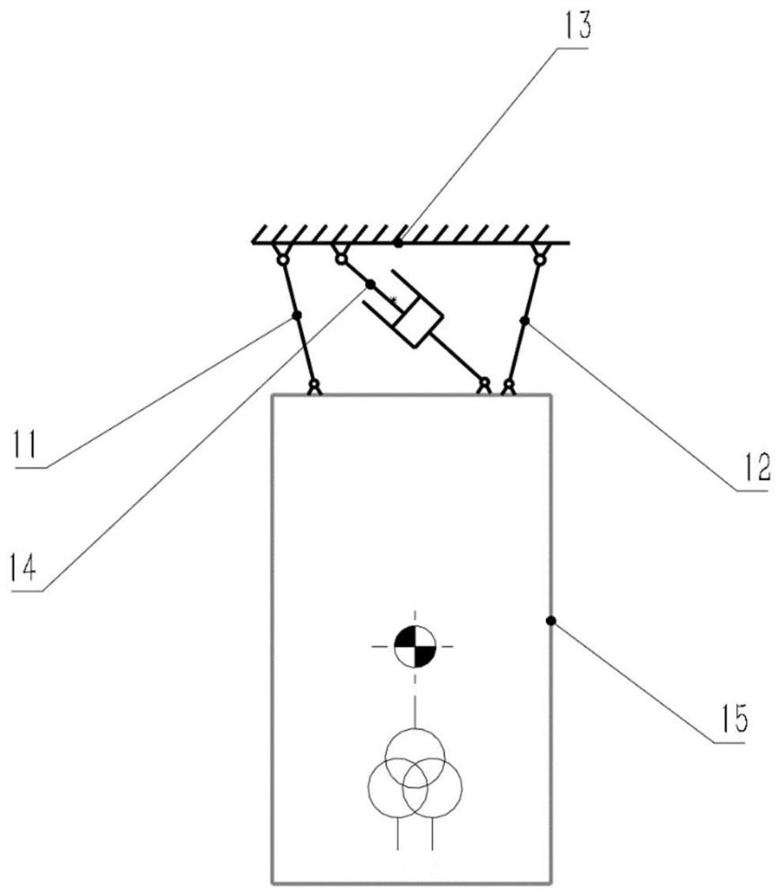
[0061] figure 1 A schematic structural diagram of Embodiment 1 of the wind power generation device provided by the embodiment of this specification. Such as figure 1 As mentioned above, the wind power generation device includes: a first connecting rod 11 , a second connecting rod 12 , a generator set body structure 13 , a damping device 14 and a large mass element 15 .

[0062] Wherein, the first connecting rod 11 and the second connecting rod 12 are respectively connected to the motor unit body structure 13 and the large mass element 15, and the connection positions of the first connecting rod 11 and the second connecting rod 12 to the motor unit body structure 13 are different, The connecting positions of the first connecting rod 11 , the second connecting rod 12 and the large mass element 15 are also different. The first connecting rod 11, the second connecting rod 12, the generator set body structure 13 and the large mass element 15 form a four-bar mechanism. The large ...

Embodiment 2

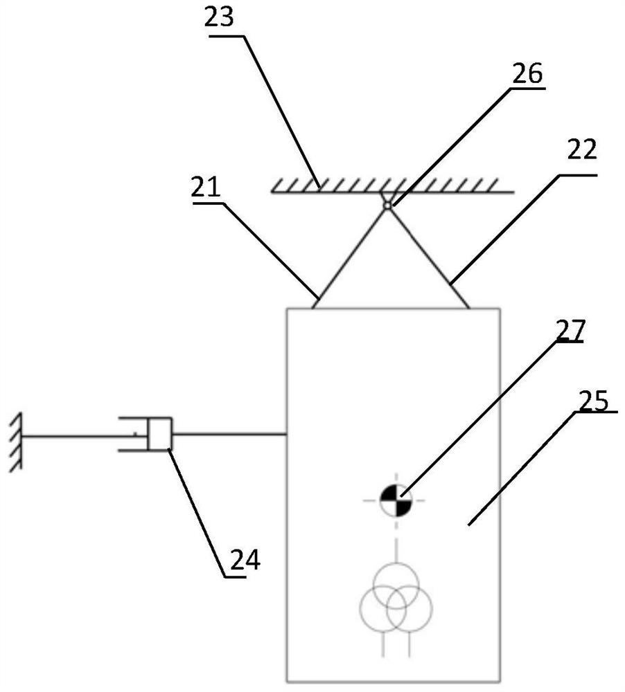
[0066] figure 2 The schematic structural diagram of the second embodiment of the wind power generation device provided by the embodiment of this specification. Such as figure 2 As mentioned above, the wind power generation device includes: a first connecting rod 21 , a second connecting rod 22 , a generator set body structure 23 , a damping device 24 and a large mass element 25 .

[0067] The difference from Embodiment 1 is that the connecting points of the first connecting rod 21, the second connecting rod 22 and the motor unit body structure 23 are the same point 26, and the point 26 is the rotation center of the large mass element 25. In addition, the point 27 is the center of gravity of the mass element 25. One end of the damping device 24 is connected to the mass element 25 , and the other end is connected to the side of the generator set body structure 23 .

[0068] In this embodiment, the center of rotation of the mass element 25 is outside it.

Embodiment 3

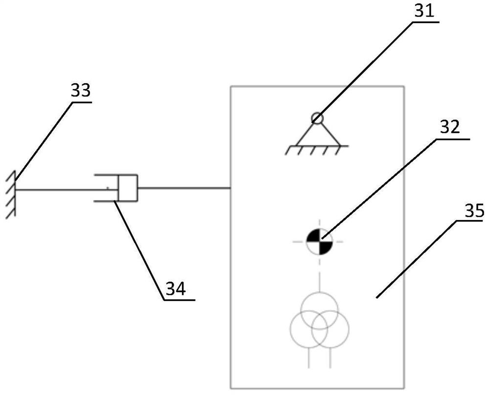
[0070] image 3 The schematic structural diagram of the third embodiment of the wind power generation device provided by the embodiment of this specification. Such as image 3 As mentioned above, the wind power generation device includes: a generator set body structure 33 , a damping device 34 and a large-mass element 35 , wherein point 31 is the rotation center of the large-mass element 35 , and point 32 is the center of gravity of the large-mass element 35 . In this embodiment, the center of rotation of the mass element 25 is inside it.


PUM


Abstract

The embodiment of the invention discloses a wind power generation device and a mounting method thereof. The device comprises a large-mass element, a damping device and a generator set main structure,wherein the large-mass element is connected with the generator set main structure through a movable connecting piece and can move relative to the generator set main structure through the movable connecting piece, one end of the damping device is connected with the large-mass element, the other end of the damping device is connected with the generator set main structure or the movable connecting piece, and the damping device is used for slowing down the relative movement. Through the device, the dynamic characteristics of a whole wind generator set can be improved while the mounting and connecting requirements of a transformer and other components are met, and the effects of dissipating energy and reducing vibration also can be achieved during vibration of the generator set main structure.

Description

technical field [0001] The embodiments of this specification relate to the technical field of wind power generators, and in particular to a wind power generation device and an installation method thereof. Background technique [0002] Wind energy is a renewable, green and environment-friendly energy source. In the context of global energy shortage and increasingly serious environmental pollution, wind power generation is effectively developed and utilized. Its development prospects are considerable both in terms of economic and social benefits. Compared with other energy sources, wind energy has obvious advantages. It has a large reserve, which is 10 times that of water energy. It is widely distributed and never exhausted. Wind power generation is the most common form of wind energy used by contemporary people. Has developed rapidly. [0003] The wind energy is converted into mechanical energy through the impeller, and the generator converts the mechanical energy into elect...

Claims


Application Information

Patent Timeline
Patent Type & Authority Applications(China)
IPC IPC(8): F03D80/80
CPCF03D80/82F03D80/88Y02E10/72
Inventor 罗安菄
Owner MECAL(北京)工程技术有限公司
Why Eureka
Try Eureka