Internal combustion type wastewater treatment equipment
A technology for wastewater treatment and equipment, applied to the field of internal combustion wastewater treatment equipment, can solve the problems of reducing the heat conduction effect of bottom heating, reducing the effect of wastewater incineration treatment, and slow temperature conduction of the top layer of wastewater, so as to speed up comprehensive high-temperature reaction and prevent wastewater from floating. , the effect of improving the transmission capacity
- Summary
- Abstract
- Description
- Claims
- Application Information
AI Technical Summary
Problems solved by technology
Method used
Image

Examples
Embodiment 1
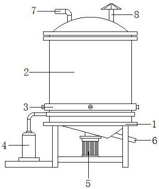
[0022] as attached figure 1 to attach Figure 5 Shown:
[0023] The present invention is an internal combustion waste water treatment equipment, the structure of which comprises a support frame 1, a processing main engine 2, an intake pipe 3, a liquefied gas tank 4, a motor 5, a drain pipe 6, a waste water inlet 7, and an exhaust pipe 8. The support frame The upper end of 1 is welded to the outer side of the lower end of the processing host 2, the lower end of the processing host 2 is embedded with an intake pipe 3 and communicates with each other, the liquefied gas tank 4 is fixedly installed on the lower left end of the support frame 1, and the upper end of the liquefied gas tank 4 is connected to the processing The left lower end of the main machine 2 is connected, the motor 5 is arranged at the bottom of the outer side of the processing main machine 2, the drainage pipe 6 is embedded and installed at the lower end of the main processing main machine 2 and connected with e...
Embodiment 2
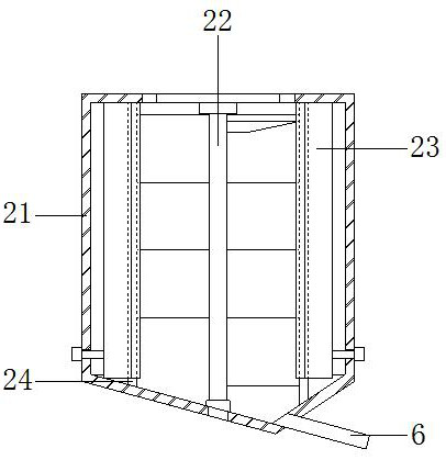
[0030] as attached Figure 6 to attach Figure 7 Shown:
[0031] Wherein, the heating mechanism 23 includes an air inlet 23a, a guide ring 23b, an ignition tube 23c, and a fire outlet mechanism 23d. 23a is located inside the left end of the guide ring 23b and communicates with each other. The inner side of the guide ring 23b is embedded with an ignition tube 23c, and the inner end of the ignition tube 23c is fixedly equipped with a fire outlet mechanism 23d, and the fire outlet mechanism 23d is located on the inner cavity wall 24 On the outside, the guide ring 23b has a ring-shaped structure and is located at the same center as the inner cavity wall 24. The four directions inside the guide ring 23b are provided with ignition tubes 23c, and the ignition tubes 23c have a wide inlet and a narrow outlet. The structure ensures that the flame inside the guide ring 23b is sprayed out from the four ignition tubes 23c respectively, and transmitted to the four fire outlet mechanisms 2...
PUM
 Abstract
Description
Claims
Application Information