
Automatic focusing system for laser manufacturing

An automatic focusing and laser technology, applied in optics, optical components, microscopes, etc., can solve the problems of difficult to observe focusing, the automatic focusing detector does not provide a movable bracket, and the system structure is complex, achieving a wide range of applications and low cost. , the effect of high motion precision

Active Publication Date: 2021-01-01
TSINGHUA UNIV
View PDF3 Cites 2 Cited by
  • Summary
  • Abstract
  • Description
  • Claims
  • Application Information

AI Technical Summary

Problems solved by technology

[0004] The above-mentioned automatic focusing system has the following defects: 1) the system structure is complex, requiring a large number of optical components to build the required optical path; 2) mainly using photoelectric sensors, it is difficult to observe the focusing situation intuitively during the manufacturing process; 3) the automatic focusing detection of the device The device does not provide relevant movable brackets, so it is not possible to fine-tune the position

Method used


Image

  • Automatic focusing system for laser manufacturing
  • Automatic focusing system for laser manufacturing
  • Automatic focusing system for laser manufacturing

Examples


Embodiment 1

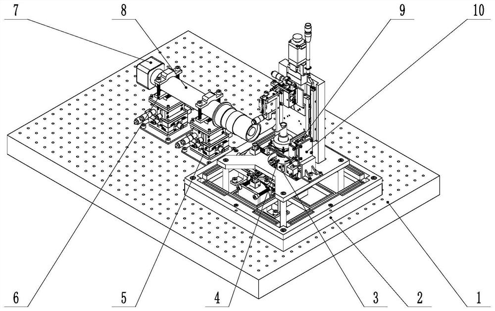
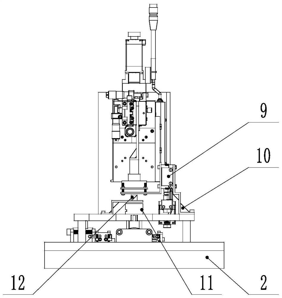
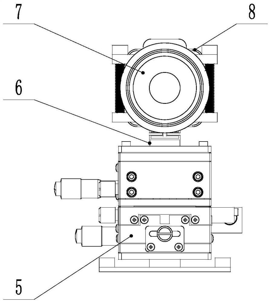
[0035] The invention provides an automatic focusing system for laser manufacturing, which includes an installation platform, an optical module, an image acquisition module, a precision position adjustment module, an image processing module, a communication module and a motion control module.

[0036] The image acquisition system collects the spot image of the laser on the processing surface, processes it through the image processing module, and completes the laser automatic focusing through the motion control module. The precise position adjustment module can fine-tune the position of the image acquisition module to facilitate capturing the spot in the field of view; through the reasonable design of the optical module, the automatic focus and real-time monitoring of the laser spot can be realized while the processing is in progress.

[0037] The installation platform includes a base 1 and a motion platform 2; the optical module includes a laser light source 3, a lens 11, a beam...

Embodiment 2

[0054] This embodiment is basically the same as Embodiment 1. For the sake of brevity, in the description process of this embodiment, the same technical features as Embodiment 1 will not be described, and only the differences between this embodiment and Embodiment 1 will be described:

[0055] Further, the image processing algorithm may be an image processing algorithm based on the minimum circumscribed circle of the light spot. The specific process of the algorithm is as follows:

[0056] Firstly, the image is collected, the image is processed in grayscale, and the grayscale image is binarized according to the preset threshold. In order to eliminate the influence of image noise, median filtering is performed. In this embodiment, a 3×3 filtering window is selected. In the processed image, the pixels at the spot are white, and the rest are black. Use the minimum circumscribed circle to envelop all white pixel values. In order to avoid collecting small spots when they are not ...


PUM


Abstract

The invention provides an automatic focusing system for laser manufacturing. The automatic focusing system comprises a mounting platform, an optical module, an image acquisition module, a precise position adjusting module, an image processing module, a communication module and a motion control module, wherein the image acquisition system acquires a light spot image of the laser on a machining surface, the image is processed by the image processing module, and automatic laser focusing is completed by the motion control module; the precise position adjusting module can finely adjust the positionof the image acquisition module, so that light spots can be conveniently captured in a visual field; and through reasonable design of the optical module, automatic focusing and real-time monitoring of laser spots can be realized while processing is carried out. The automatic focusing system can realize automatic focusing of a desktop-level high-precision laser micro-nano manufacturing device at the machining surface, has the advantages of being low in cost, high in motion precision, large in adjusting range, high in flexibility, modular in structure, wide in application range and the like, has high application value and can be widely applied to the focusing process in laser manufacturing.

Description

technical field [0001] The invention belongs to the field of optical microscopic imaging, and relates to a microscopic autofocus device and method, in particular to an autofocus system for laser manufacturing based on computer vision. Background technique [0002] At present, the research on micro-optical imaging and auto-focusing system is gradually rising, which has a wide range of application prospects, such as laser direct writing, laser scanning galvanometer, parts inspection, IC equipment and biomedicine. The general autofocus system has the following characteristics: non-contact measurement; judge whether it has been focused by the clarity of the image; use piezoelectric ceramics for driving; have its own optical system and control system; have a certain focus accuracy. [0003] Existing autofocus systems include autofocus light sources, optical components, focus lenses, autofocus detectors, and autofocus processing components. The focus of the optics is continuously...

Claims


Application Information

Patent Timeline
Patent Type & Authority Applications(China)
IPC IPC(8): G02B21/24G02B21/26G02B21/36
CPCG02B21/241G02B21/26G02B21/361G02B21/365
Inventor 张震刘义杰余良曹宇轩
Owner TSINGHUA UNIV
Learn More