Stirring machine cleaning device
A technology for cleaning devices and mixers, which is applied to valve devices, spray devices, mechanical equipment, etc., and can solve problems such as clogged nozzles that cannot continue to work, splashes and solidification, etc., to ensure work efficiency and improve cleaning effects.
- Summary
- Abstract
- Description
- Claims
- Application Information
AI Technical Summary
Problems solved by technology
Method used
Image
Examples
Embodiment 1
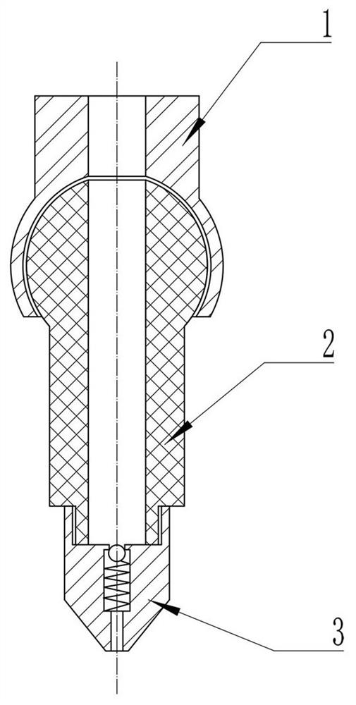
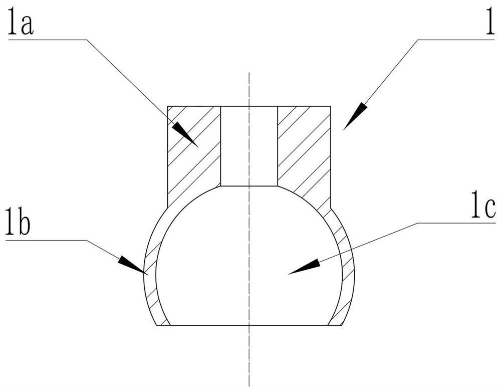
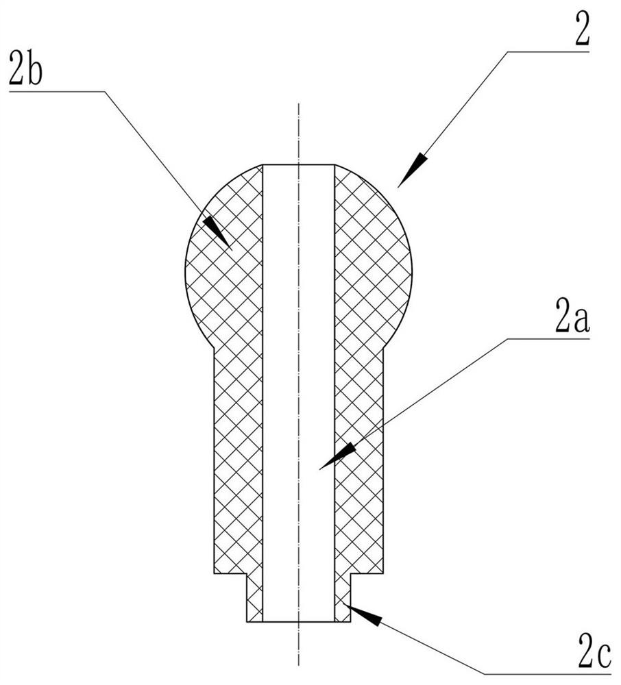
[0049] Embodiment 1: A spray head includes three parts: a mounting base 1 , an adjusting connector 2 and a nozzle 3 . The main body of the installation support 1 is a hollow cylindrical shape and the installation support 1 can be divided into the upper side, which is provided with a fixed installation part 1a for connecting with the water pipe 10 through screw fit, and the lower side. The mating connection part 1b on the side is used to connect with the adjustment connector; specifically, the said mating connection part 1b has a spherical shape whose radial dimension is larger than that of the fixed installation part 1a. A hollow spherical accommodating space 1c for clamping with the adjustment connecting piece 2 is formed in 1b. The main body of the adjustment connector 2 is cylindrical, and a hollow flow guide space 2a extending along its own axial direction and passing through both ends of the adjustment connector 2 is provided inside the adjustment connector 2; The upper ...
Embodiment 2
[0050] Embodiment 2: On the basis of the spray head described in Embodiment 1, a radial dimension slightly larger than the radial dimension of other sections of the spray opening 3a is set at the spray opening 3a in the nozzle 3 for installation of one-way The installation space 3c of the valve 4. The one-way valve 4 includes a spring 4b and a steel ball 4a. The spring 4b is compressed to a certain extent in the initial installation state, and its lower end abuts against the lower end surface of the installation space 3c, and the upper end of the spring 4b abuts against the steel ball 4a arranged there and presses against the steel ball 4a. The ball 4a generates an upward abutting force, so that the upper part of the steel ball 4a abuts against the upper end surface of the installation space 3c. The one-way valve structure can ensure that only when the pressure inside the water pipe 10 that supplies water to the nozzle reaches a certain size, can the one-way valve 4 be opened...
Embodiment 3
[0054] Embodiment 3: a mixer cleaning device comprising the nozzle described in Embodiment 1 or Embodiment 2, also includes a water pipe 10 for providing water for the nozzle, the water pipe is installed on the top of the mixer main body 9 and divided They are arranged on both sides of the mixer main shaft 8, and the various positions of the mixer main shaft 8 are fully and effectively washed by adjusting the angle direction of the nozzle installed on the water pipe 10.
[0055] The interior of the mixer cleaning device is also equipped with a plurality of monitoring probes, which can observe the inside of the mixer in real time, and detect whether each nozzle of the mixer cleaning device is working normally or whether the angle of the nozzle after debugging can achieve ideal cleaning. As a result, this structure also saves the work of staff to observe and monitor the mixer, and improves the safety of the mixer cleaning device while improving work efficiency.
PUM
 Abstract
Description
Claims
Application Information
 - R&D
- Intellectual Property
- Life Sciences
- Materials
- Tech Scout
- Unparalleled Data Quality
- Higher Quality Content
- 60% Fewer Hallucinations
Browse by: Latest US Patents, China's latest patents, Technical Efficacy Thesaurus, Application Domain, Technology Topic, Popular Technical Reports.
© 2025 PatSnap. All rights reserved.Legal|Privacy policy|Modern Slavery Act Transparency Statement|Sitemap|About US| Contact US: help@patsnap.com


